
E-fixture

Inactive Publication Date: 2006-05-18
THE BOEING CO
View PDF3 Cites 52 Cited by
  • Summary
  • Abstract
  • Description
  • Claims
  • Application Information

AI Technical Summary

Benefits of technology

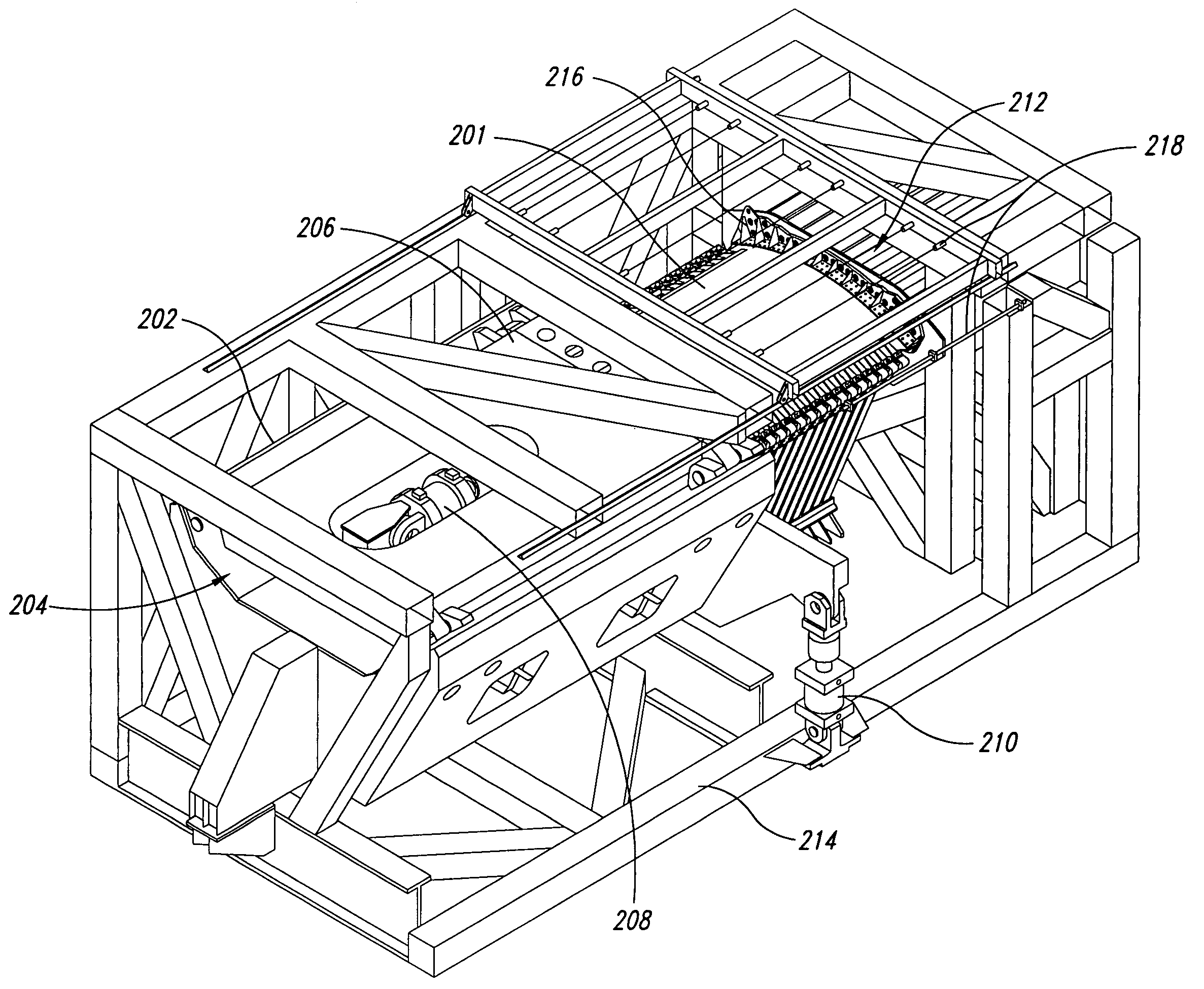
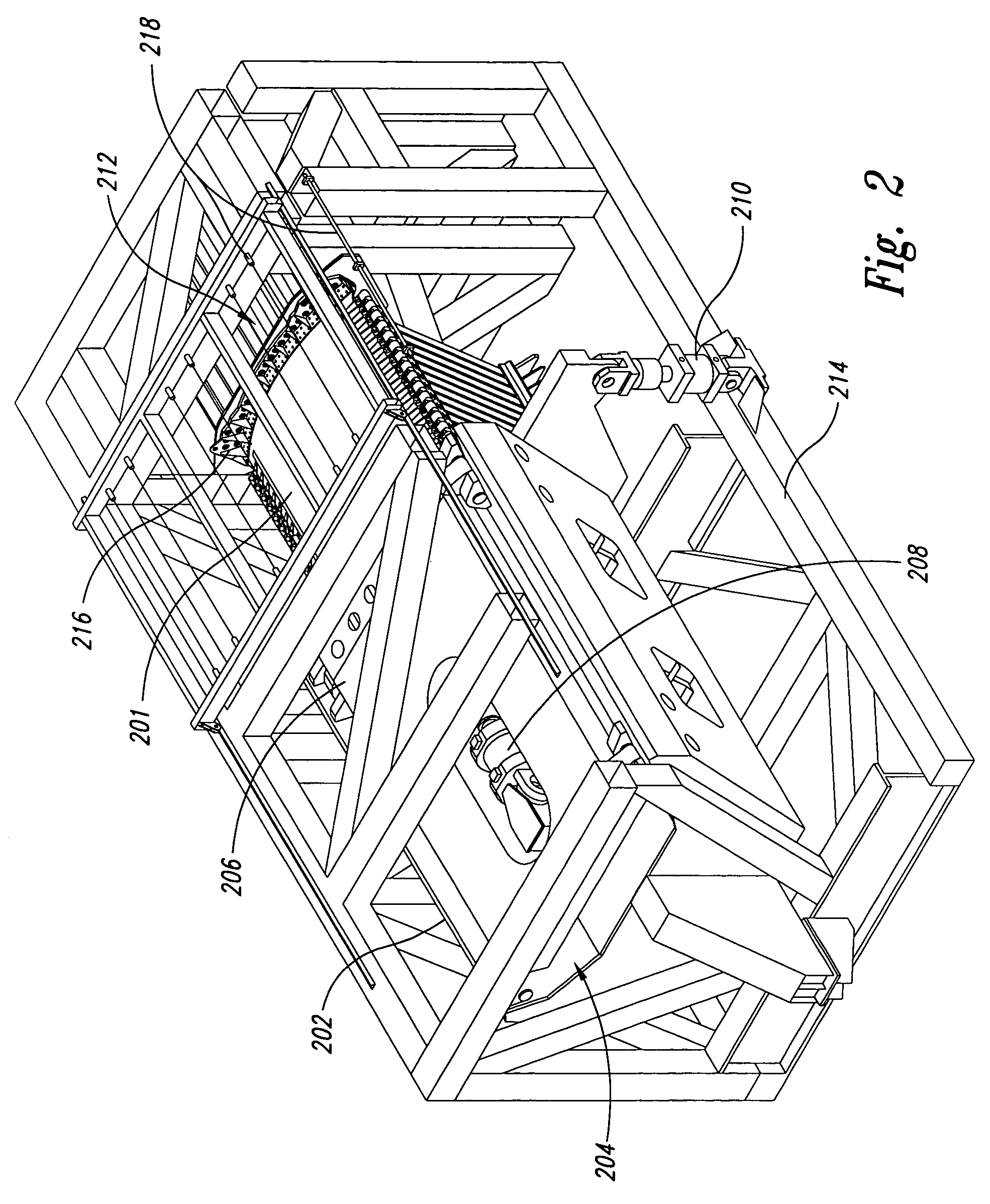
[0009] The present invention provides a common fixture, named E-Fixture, for testing curved fuselage skin-stringer-frame panels under realistic flight loading conditions. The E-Fixture has the capability of applying tension, compression, shear via body torsion, and pressure loads to a test panel in various combinations thereof to evaluate the ultimate static strength and fatigue spectrum loading performance of aircraft fuselage panels. The E-Fixture has the capability of applying combined static, fatigue and thermal loadings. Provisions for fast turn-around of test panel installation and testing, and accommodation of test panels with varying combinations of skin-stringer gages and lay-ups are incorporated in the design.

Problems solved by technology

During the past few decades, aircraft safety has been an important issue to design and maintenance engineers.
Aircraft fuselage panels are subject to various types of loadings during normal operations and can develop cracks or failures by the process of fatigue.
Such cracks grow slowly with increasing time and service, finally reaching a critical length of crack that can cause rapid propagation and catastrophic failure of an aircraft.
However, the COLTS facility has the following characteristics: 1) an extensive FEM modeling is required to determine proper shear reaction, 2) it is difficult to develop full hoop loading in combination with torsion loading, and 3) the facility requires complex control algorithms.
However, the FASTER facility fails to apply compression loading to the panel and the success of shear box performance may be questionable.
However, it is not known whether the facility has the capability to load shear, compression loading or any combination thereof.
However, no attempt to apply full body loading has been made in that facility and test results are questionable.
However, the facility has no internal pressurization mechanism, and therefore, cannot develop hoop loading.
Also, it does not have any structure to develop proper shear reaction on the test panel.
The panel may be subject to thermal conditioning from room temperature to 915° F. However, the facility cannot apply pressure or hoop loads as the test panels are flat.
However, this facility has not been known to test the panel under controlled pressure, hoop, or shear loading.

Method used


Image

  • E-fixture
  • E-fixture
  • E-fixture

Examples


Embodiment Construction

[0030] The following detailed description is of the best currently contemplated modes of carrying out the invention. The description is not to be taken in a limiting sense, but is made merely for the purpose of illustrating the general principles of the invention, since the scope of the invention is best defined by the appended claims.

[0031] Broadly, the present invention provides a test fixture, called the “E-Fixture”, for testing curved fuselage panels to support design and analysis of aircraft fuselage development. Unlike the existing test fixtures, the E-Fixture has the capability of simultaneously applying tension, compression, shear, hoop and pressure loads, individually or in combination, to the test panel to evaluate the ultimate static strength and fatigue spectrum loading performance of aircraft fuselage panels. Such a capability can validate design / analysis methods for combined loadings of pre- and post-buckled curved fuselage panels, which is critical to the evaluation ...


PUM


Abstract

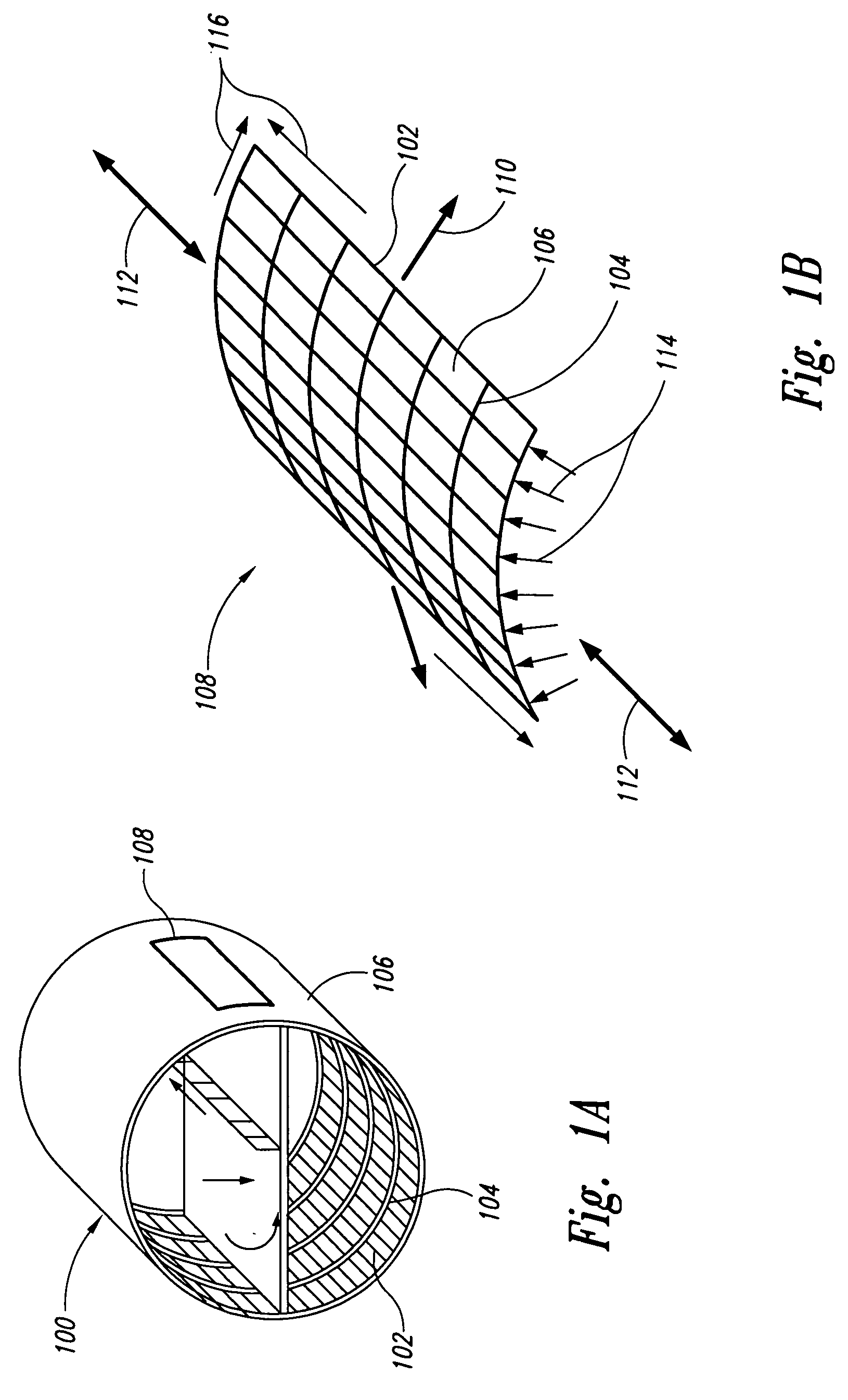
A device and a method are disclosed for testing a curved panel assembly, which simulates a segment of an aircraft fuselage barrel section, subjected to combined loading. The device includes an axial load head assembly attached to the test panel assembly via one axial load fitting and configured to apply an axial load to the test panel assembly, and an axial-torsion reaction box connected to the axial load head assembly via linear journal bearing assemblies, where the axial-torsion reaction box is configured to be rotated by a pair of torsional loading systems to apply a torsional load to the test panel assembly. The device also includes a gore section attached to hoop load fittings of the test panel assembly, configured to provide degrees of freedom that constrain the test panel assembly to load and deflect as it would naturally in an actual fuselage barrel, form a plenum box to apply an internal pressure load, and provide hoop loading systems that complete the full hoop load application to the test panel assembly. A fixed reaction box attached to the test panel assembly via another axial load fitting rigidly attaches the test panel to the self-reacting frame, completing the internal load path of the overall system.

Description

BACKGROUND OF THE INVENTION [0001] The present invention generally relates to a structural testing facility and, more particularly, to a testing facility for aircraft fuselage panels under various loading conditions. [0002] During the past few decades, aircraft safety has been an important issue to design and maintenance engineers. Aircraft fuselage panels are subject to various types of loadings during normal operations and can develop cracks or failures by the process of fatigue. Such cracks grow slowly with increasing time and service, finally reaching a critical length of crack that can cause rapid propagation and catastrophic failure of an aircraft. [0003] To understand and assess the effects of crack growth and residual strength of fuselage structures, several facilities have been developed to apply fight load conditions to large or full-scale models. For example, Rouse et al., AIAA paper No. 1423, 2003, discloses the Combined Loads Test (COLTS) facility at NASA Langley Resear...

Claims


Application Information

Patent Timeline
IPC IPC(8): G01N3/02G01N3/10G01N3/12G01N3/22G01N3/24
CPCG01N3/04G01N2203/0016G01N2203/0021G01N2203/0025
Inventor OSTGAARD, DOUGLAS R.PATEL, RAMANLAL A.MCNEIL, LEE A.
Owner THE BOEING CO
Learn More