Active beam delivery system for laser peening and laser peening method

a laser peening and laser peening technology, applied in the direction of manufacturing tools, soldering devices, auxilary welding devices, etc., can solve the problems of high workpiece specificity, inability to use, and insufficient intensity of laser peening, so as to reduce the complexity of holding fixtures and workpieces, cost and engineering, cost effective

Active Publication Date: 2006-05-18
METAL IMPROVEMENT CO INC
View PDF49 Cites 47 Cited by
  • Summary
  • Abstract
  • Description
  • Claims
  • Application Information

AI Technical Summary

Benefits of technology

[0016] A laser peening method and system, which allow the work piece to be fixed, while moving and directing the laser beam in a highly controlled manner are described. Utilizing a fixed work piece position minimizes holding fixture and work piece moving complexity, thereby reducing cost and engineering. Moving the laser beam rather than the work piece, or with limited movement of the work piece, will allow work pieces larger than automation handling capacity to be cost effectively laser peened.

Problems solved by technology

However, for many applications, shot peening does not provide sufficiently intense or deep treatment, or cannot be used because of its detrimental effect on the surface finish.
This method becomes both costly and highly work piece specific, requiring considerable engineering to develop processes for new work pieces.
In addition, work piece size is limited to the lifting and handling capacity of the automation utilized.
However, even at wavelengths where glass fiber transmission is normally high, the very high pulse energy and high peak power used in laser peening can damage the fibers and render them ineffective.
Because of its 10 μm wavelength in the far infrared, the output of a CO2 laser cannot be delivered by glass fibers.
Optical losses—A standard seven-knuckle articulated arm would require seven mirror reflections between the input and the output, introducing optical losses during beam delivery that reduce efficiency of the system.
Length limitations—Articulated arms have a fixed length, allowing limited flexibility as to placement with respect to the work piece.
However, it is still possible to damage the arm by forcing it through disallowed paths or by causing collisions with the process robot.

Method used


Image

  • Active beam delivery system for laser peening and laser peening method
  • Active beam delivery system for laser peening and laser peening method
  • Active beam delivery system for laser peening and laser peening method

Examples


Embodiment Construction

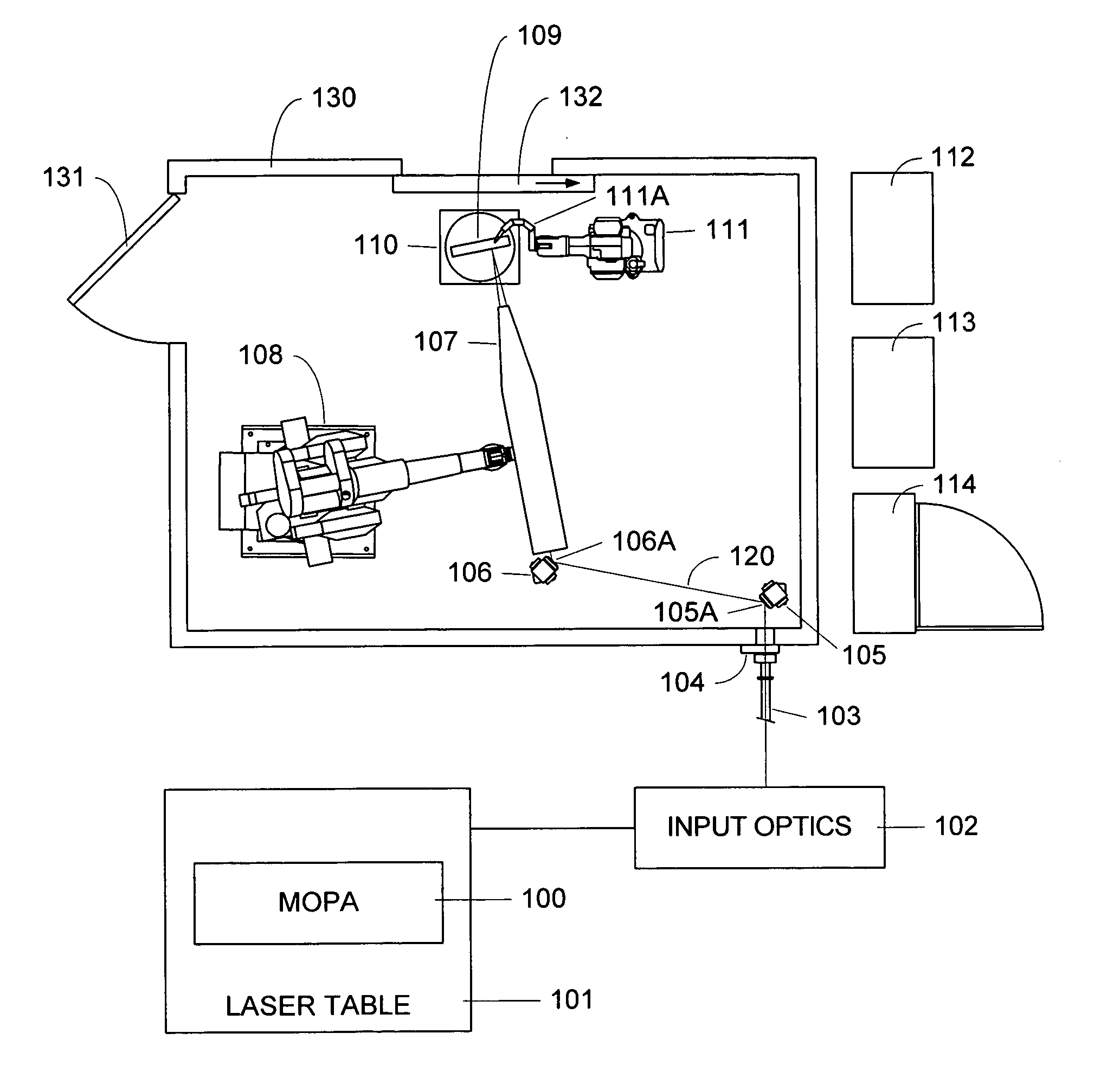
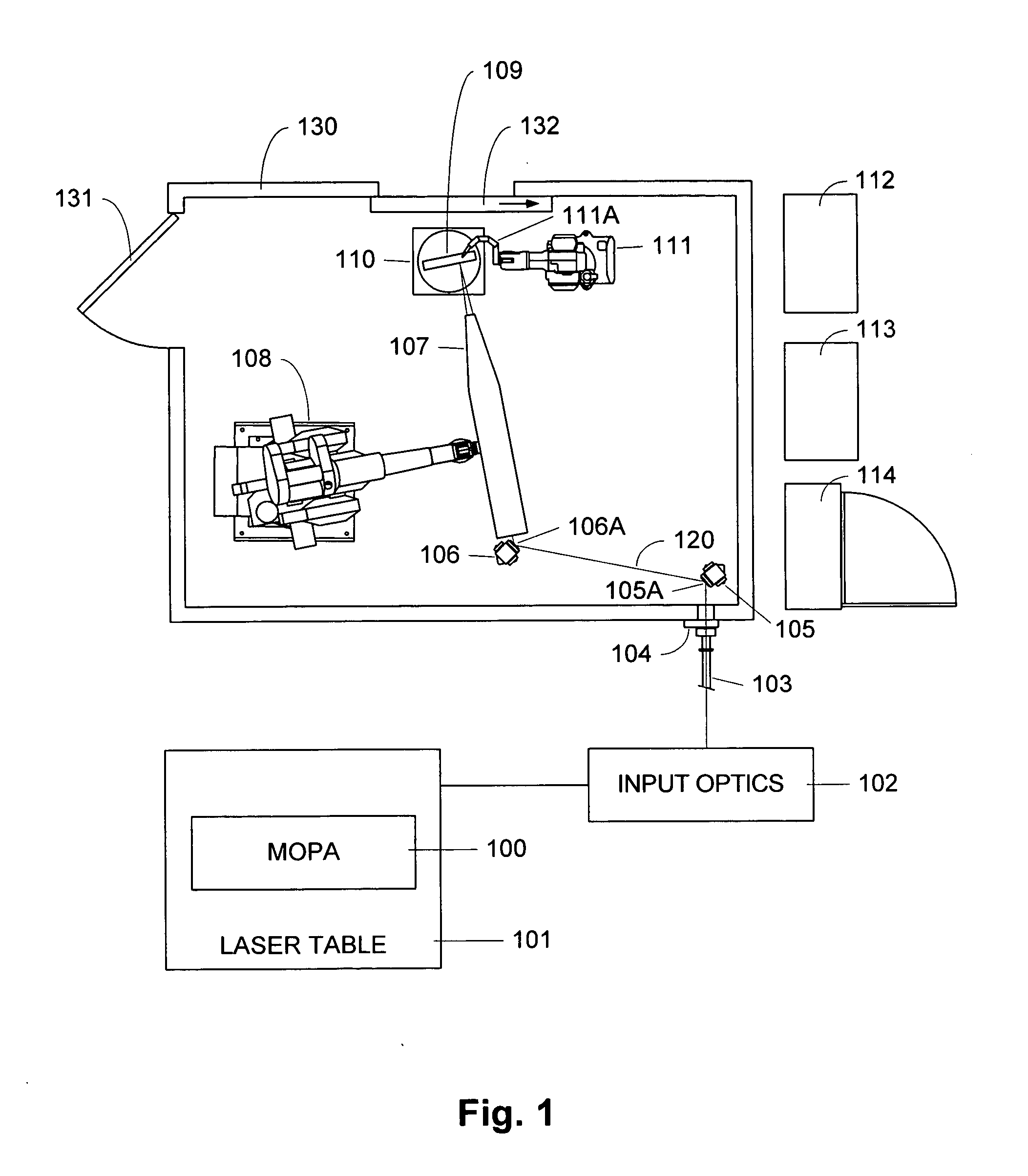
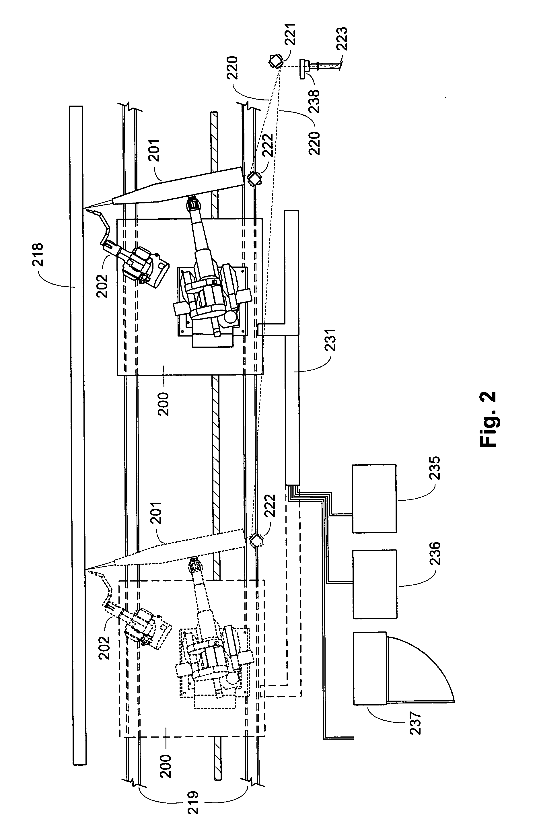
[0028] A detailed description of embodiments of the present invention is provided with reference to the FIGS. 1-7. The articulated segments and seven mirrors of a conventional energy delivery system are replaced in embodiments of the energy delivery system described herein, with two mirrors on high-speed, high-resolution gimbals. Propagation to a laser peening processing head that comprises a robot mounted optical assembly is by a free air path between the two gimbal-mounted mirrors. Beam diagnostics also located on the processing head monitor laser pointing, beam rotation, and laser energy on a shot-to-shot basis. Finally, a processing camera, located on the output of the tool, images the laser peening treatment plane.

[0029]FIG. 1 shows a schematic of a laser peening system. This is not meant to be a scale design of an actual system but illustrates basic components and their layout. The system of FIG. 1 includes a laser 100 in a master oscillator / power amplifier configuration, suc...


PUM

PropertyMeasurementUnit
lengthsaaaaaaaaaa
wavelengthaaaaaaaaaa
pulse energyaaaaaaaaaa

Abstract

A laser peening method and system allows the work piece to be fixed, while moving and directing the laser beam. A laser energy delivery system includes a relay imaging system. Input optics arranged to receive the laser energy, a transmitting mirror having adjustable angle of incidence relative to the input optics, and a robot mounted processing head including an optical assembly are configured to direct laser energy toward the movable target image plane. The laser energy follows an optical path including an essentially straight segment from the transmitting mirror to the receiving mirror, having a variable length and a variable angle relative to the input optics. Diagnostics on the processing head facilitate operation.

Description

BACKGROUND OF THE INVENTION [0001] 1. Field of the Invention [0002] The present invention relates to high energy laser systems, to beam delivery systems, and to laser peening systems suitable for use with stationary targets. [0003] 2. Description of Related Art [0004] The use of mechanical shocks to form metals and to improve their surface properties has been realized for ages. In current industrial practice, a peening treatment of metal surfaces is accomplished by using high velocity shot. Treatment improves surface properties and, very importantly for many applications, results in a part displaying significantly improved resistance to fatigue and corrosion failure. A wide range of work pieces are shot peened in the aerospace and automotive industries. However, for many applications, shot peening does not provide sufficiently intense or deep treatment, or cannot be used because of its detrimental effect on the surface finish. [0005] With the invention of the laser, it was rapidly r...

Claims


Application Information

Patent Timeline
Patent Type & Authority Applications(United States)
IPC IPC(8): B23K26/00
CPCB23K26/0069B23K26/063B23K26/0884B23K26/422B23K37/0452C21D1/09C21D10/005B23K26/0622B23K26/356B23K26/702
Inventor DANE, C. BRENTHARRIS, FRITZ B.TARANOWSKI, JOSEPH T.BROWN, STEWART B.
Owner METAL IMPROVEMENT CO INC
Why Eureka
Try Eureka