Actuator control system

a control system and actuator technology, applied in the direction of shock absorbers, cooking vessels, gearing, etc., can solve the problems of high production cost and deterioration of the durability of electric actuators, and achieve the effect of maintaining durability

Active Publication Date: 2006-05-18
SMC CORP
View PDF17 Cites 40 Cited by
  • Summary
  • Abstract
  • Description
  • Claims
  • Application Information

AI Technical Summary

Benefits of technology

[0012] A general object of the present invention is to provide an actuator control system which makes it possible to maintain the durability by appropriately absorbing the impac

Problems solved by technology

However, when the electric actuator, according to the conventional technique disclosed in Japanese Laid-Open Patent Publication No. 11-30234 as described above, is applied, for example, to the pressing operation for the workpiece, for example, at any intermediate position between one stroke end and the other stroke end in accordance with the back and forth movement performed similarly to a piston rod of a fluid pressure cylinder without using any complicated control apparatus or the like, the durability of the electric actuator is deteriorated, because the shock or impact, which is c

Method used


Image

  • Actuator control system
  • Actuator control system
  • Actuator control system

Examples


Embodiment Construction

;

[0038]FIG. 24 is a block diagram illustrating an arrangement of a servo circuit concerning Comparative Example 2;

[0039]FIG. 25 is a perspective view in which a plurality of attachment fixtures are installed to the electric actuator shown in FIG. 2;

[0040]FIG. 26 is a perspective view in which a cover member having an open upper surface is installed to the electric actuator shown in FIG. 25;

[0041]FIG. 27 is a perspective view in which a cover member having no opening is installed to the electric actuator shown in FIG. 25;

[0042]FIG. 28 is a perspective view in which a sensor is installed to a long groove of the cover member shown in FIG. 27;

[0043]FIG. 29 is a perspective view illustrating an electric actuator having another structure;

[0044]FIG. 30 is a partial longitudinal sectional view taken along a line XXX-XXX shown in FIG. 29;

[0045]FIG. 31 is a magnified vertical sectional view taken along a line XXXI-XXXI shown in FIG. 30;

[0046]FIG. 32 is a perspective view illustrating ...


PUM


Abstract

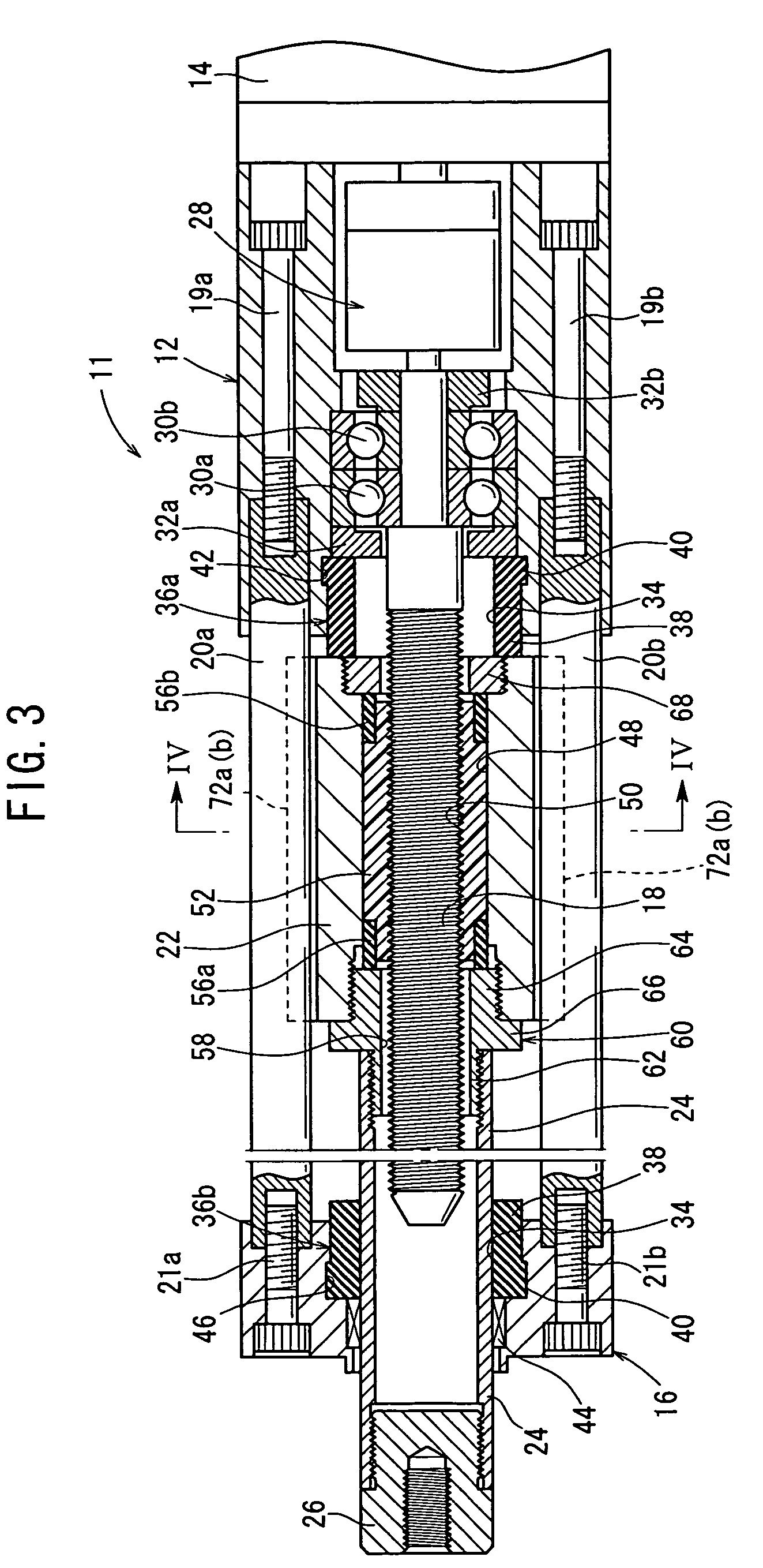
An actuator control system comprises an electric actuator, a driver, and a controller. The electric actuator is provided with a buffering mechanism which absorbs impact applied to a piston rod. The buffering mechanism includes piston dampers which absorb impact applied to a piston, a first end damper which is provided at an end of a housing facing the piston, and a second end damper which is provided on a rod cover separated from the housing by a predetermined distance.

Description

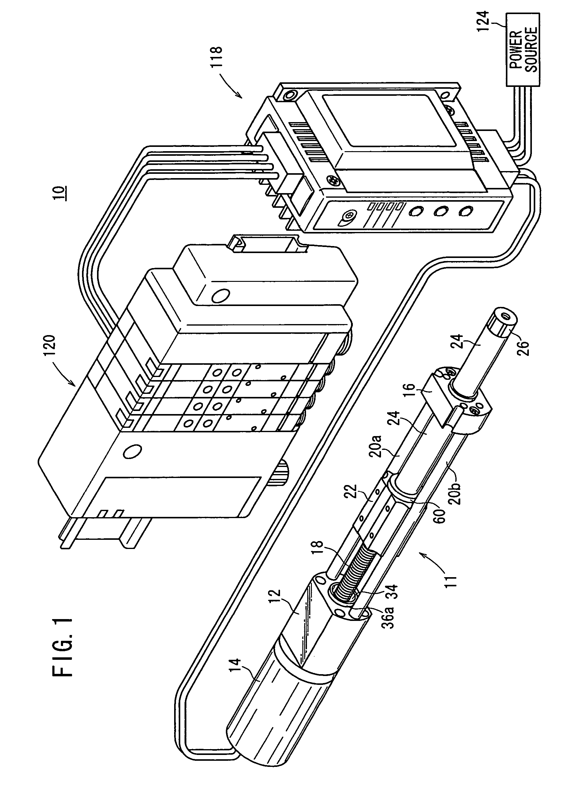
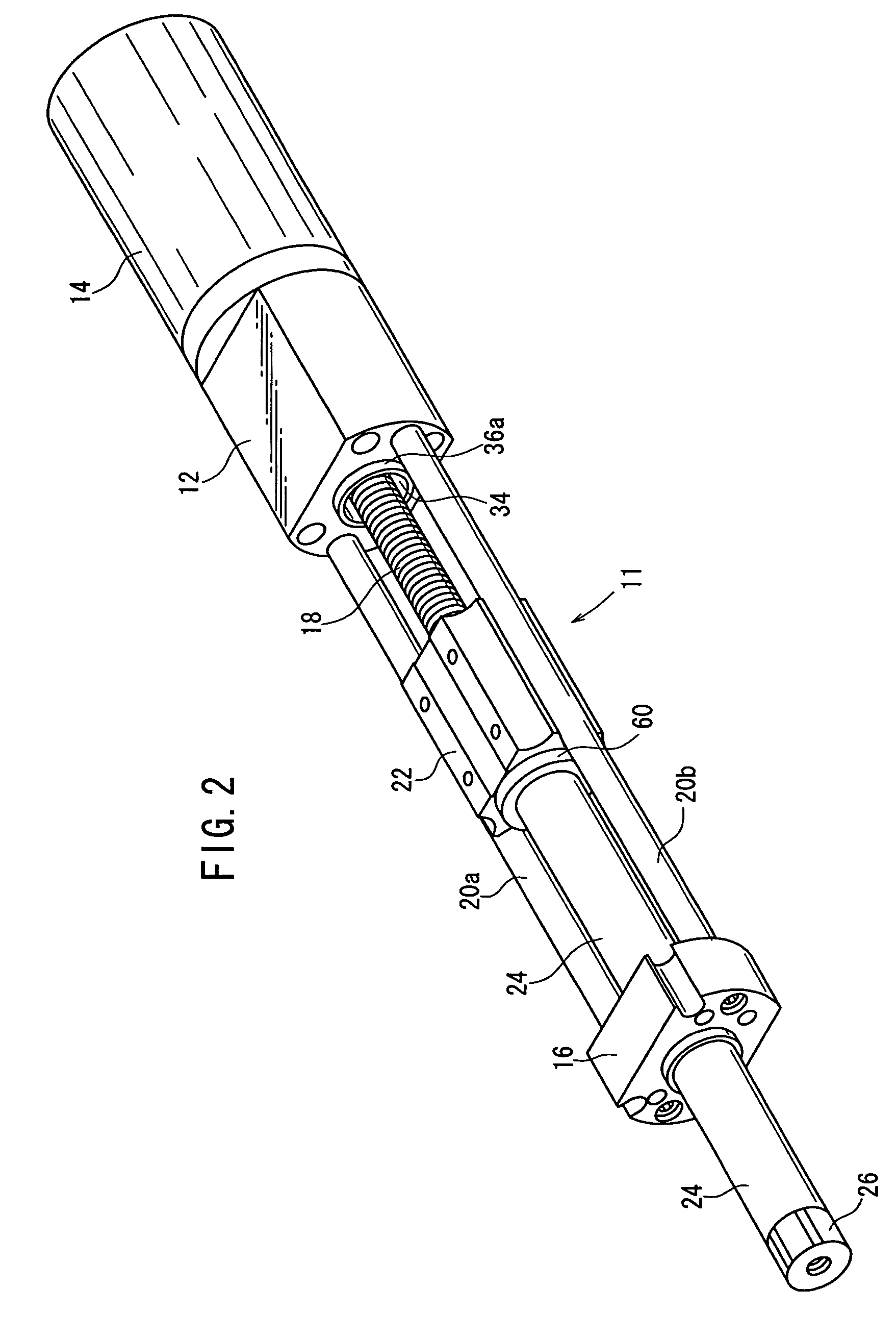
BACKGROUND OF THE INVENTION [0001] 1. Field of the Invention [0002] The present invention relates to an actuator control system comprising, for example, an electric actuator which allows a displacement member to make linear reciprocating motion under the rotary driving action of a rotary driving source, and a control unit which protects the rotary driving source for driving the electric actuator. [0003] 2. Description of the Related Art [0004] A transport means such as an actuator has been hitherto used, for example, in order to transport a workpiece. [0005] An electric actuator concerning the conventional technique is shown in FIGS. 63 and 64 (see, for example, Japanese Laid-Open Patent Publication No. 11-30234). [0006] The electric actuator 1 concerning the conventional technique has a slider 4 which is displaceable along a recess 3 of a frame 2, and a screw shaft 6 which is driven by an unillustrated motor and which is screwed to a nut member 5 that is detachable with respect to ...

Claims


Application Information

Patent Timeline
IPC IPC(8): A47J36/02F16H1/28F16F7/00F16H25/20H02K7/116H02P29/00
CPCF16H25/2021F16H2025/204F16H2025/2075F16H2025/2087H02K5/24H02K7/06F15B13/00F15B15/00
Inventor NAGAI, SHIGEKAZUSAITOH, AKIOSUGIYAMA, TORUMASUI, RYUICHIHIROSE, TAKESHIMIYAHARA, MASAKI
Owner SMC CORP
Why Eureka
Try Eureka