Scan driver, light emitting display using the same, and driving method thereof
a technology of light-emitting display and scan driver, which is applied in the direction of electroluminescent light sources, static indicating devices, instruments, etc., can solve the problems of deteriorating aperture ratio, increasing power consumption of scan driver, and relatively heavy weight of crt display, so as to reduce the number of emission control lines, enhance the aperture ratio, and facilitate fabrication
- Summary
- Abstract
- Description
- Claims
- Application Information
AI Technical Summary
Benefits of technology
Problems solved by technology
Method used
Image
Examples
first embodiment
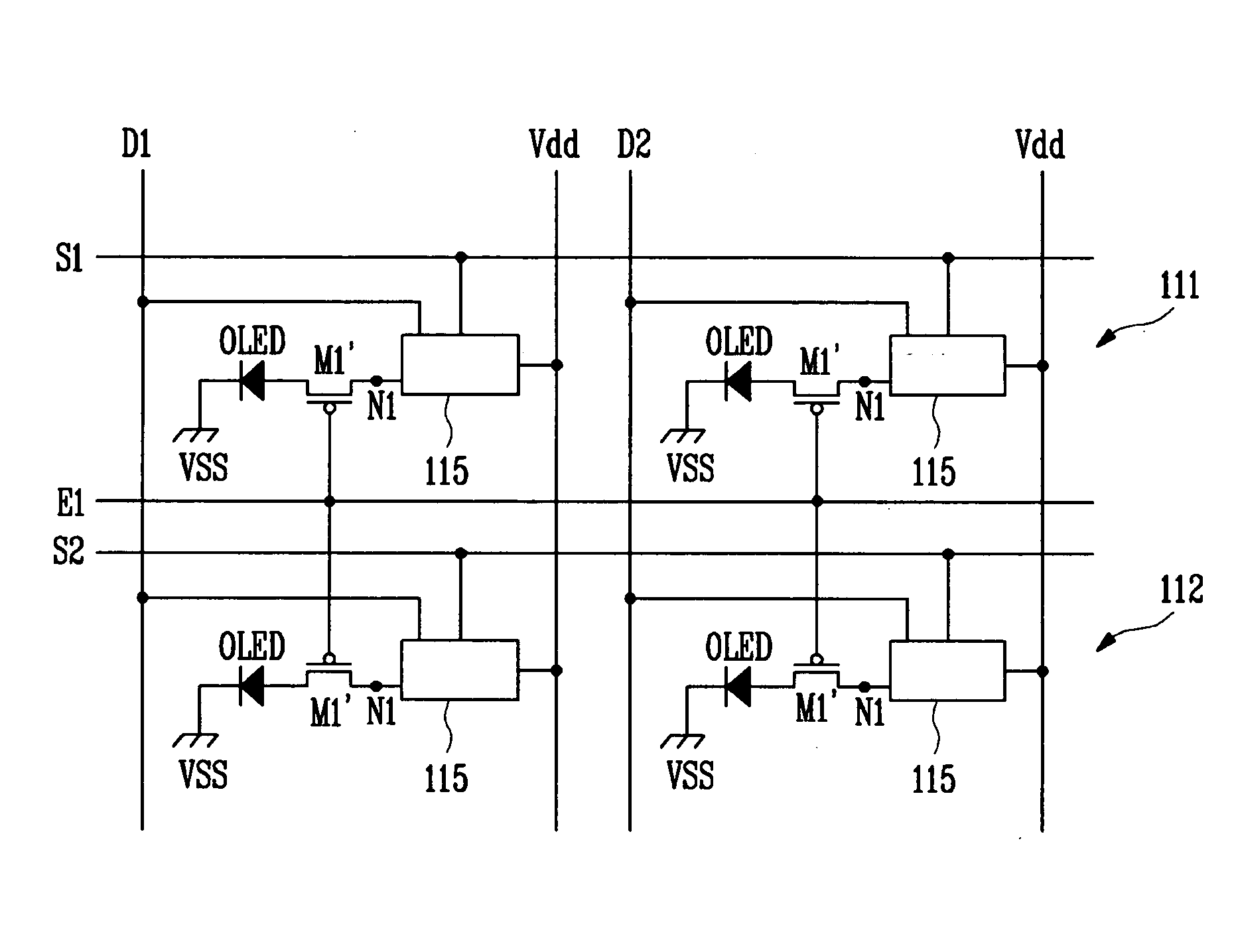
[0076]FIG. 10 is a circuit diagram of a current generator according to an exemplary embodiment of the present invention. By way of example, the current generator of FIG. 10 may be used as one or more of the current generators 115, 115′, 415 and 415′ of FIGS. 3, 5, 7 and 9. Referring to FIG. 10, the current generator includes a second transistor M22, a third transistor M23, and a capacitor Cst′. Here, each of the second transistor M22 and the third transistor M23 includes a gate, a source and a drain. Further, the capacitor Cst′ includes a first electrode and a second electrode.
[0077] The second transistor M22 includes the source connected to a power line Vdd, the drain connected to a first node N, and the gate connected to a second node A′. Here, the second node A′ is connected to the drain of the third transistor M23. The second transistor M22 supplies a current corresponding to the data signal to a light emitting device OLED.
[0078] The third transistor M23 includes the source con...
second embodiment
[0088]FIG. 12 is a circuit diagram of a current generator according to an exemplary embodiment of the present invention. By way of example, the current generator of FIG. 10 may be used as one or more of the current generators 115, 115′, 415 and 415′ of FIGS. 3, 5, 7 and 9, respectively. Referring to FIG. 12, the current generator includes second through sixth transistors M32, M33, M34, M35 and M36, and a capacitor Cst″. Here, each of the second through sixth transistors M32 through M36 is a p-channel metal oxide semiconductor (PMOS) transistor, and includes a gate, a source and a drain. Further, the capacitor Cst″ includes a first electrode and a second electrode. In the described embodiment, there may not be any physical differences between each drain and each source of the second through sixth transistors M32 through M36. Alternatively, the source, the drain and the gate may be referred to as first, second and third electrodes, respectively.
[0089] The current generator of FIG. 12 ...
PUM
 Abstract
Description
Claims
Application Information
 - R&D
- Intellectual Property
- Life Sciences
- Materials
- Tech Scout
- Unparalleled Data Quality
- Higher Quality Content
- 60% Fewer Hallucinations
Browse by: Latest US Patents, China's latest patents, Technical Efficacy Thesaurus, Application Domain, Technology Topic, Popular Technical Reports.
© 2025 PatSnap. All rights reserved.Legal|Privacy policy|Modern Slavery Act Transparency Statement|Sitemap|About US| Contact US: help@patsnap.com


