System and method for precharging and discharging a high power ultracapacitor pack

a high-power ultracapacitor and ultracapacitor technology, which is applied in the direction of motor/generator/converter stopper, process and machine control, electric devices, etc., can solve the problem of too high voltage to allow direct connection to the ultracapacitor, and achieve the effect of tight equalization

Inactive Publication Date: 2006-05-18
SHEPPARD MULLIN RICHTER & HAMPTON
View PDF7 Cites 58 Cited by
  • Summary
  • Abstract
  • Description
  • Claims
  • Application Information

AI Technical Summary

Benefits of technology

[0017] In a further aspect of the invention, the ultracap pack is immediately discharged through the braking resistor for service and maintenance safety, and as an end-of-the-day turn-off for quicker equalization in the ultracap pack without having to depend on the much slower leak-down discharging current across the passive parallel resistors within the ultracap pack. The immediate discharge may be accomplished through Siemens DUO-Inverter switches shown and described herein. Different embodiments may use other inverters and switches.
[0018] In another aspect of the inventio...

Problems solved by technology

In general, the voltage is too high to allow a direct connection to the ultracapacitors.
However, when there is no energy storage or the energy storage is charged to capacity ...

Method used


Image

  • System and method for precharging and discharging a high power ultracapacitor pack
  • System and method for precharging and discharging a high power ultracapacitor pack
  • System and method for precharging and discharging a high power ultracapacitor pack

Examples


Embodiment Construction

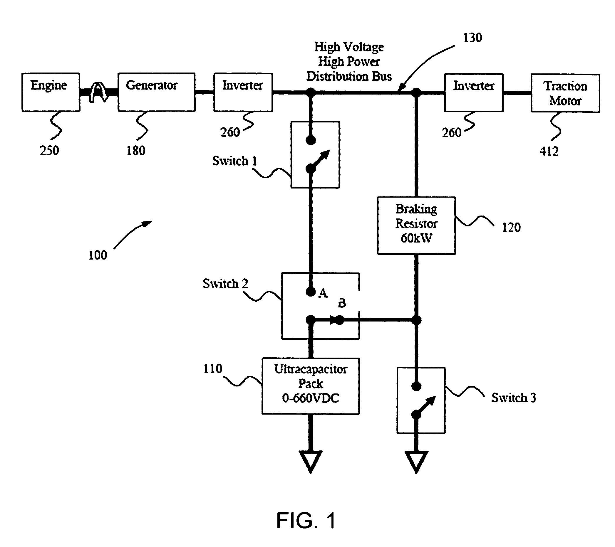
[0030] With reference to FIG. 1, the block diagram depicts an embodiment of a hybrid-electric drive system 100 with an ultracapacitor pack 110 for energy storage and a braking resistor 120 for extra deceleration power dissipation. For normal operation switch 1 is closed and switch 2 is in the A position, connecting the ultracapacitor pack 110 to the power bus 130, and switch 3 is closed whenever it is desired to use the braking resistor 120. With switch 1 open, switch 3 open, and switch 2 in the B position the braking resistor 120 is connected in series with the ultracapacitor pack 110. Thus, the ultracapacitor pack 110 can be charged from the power bus 130 through the braking resistor 120. Switch 2 and the connection to the braking resistor 120 are the only additions to the hybrid-electric drive connection for allowing the hybrid-electric drive connection to be used for precharging the ultracapacitor pack 110 through the high-power braking resistor 120. This saves the expense of a ...


PUM


Abstract

This invention is a system and a method that uses the braking resistor, commonly used and available in electrically or hybrid-electrically propelled vehicles, to limit the precharge current during the startup of a high power ultracapacitor pack energy storage device and/or safely and rapidly discharge an ultracapacitor pack for maintenance work or storage to lengthen the life of the individual ultracapacitor cells and, correspondingly, the whole pack. The use of the braking resistor for precharging an ultracapacitor energy storage pack is an effective and less expensive method compared to other methods such as a separate DC-to-DC converter. This method includes the control logic sequence to activate and deactivate switching devices that perform the connections for the charging and discharging current paths.

Description

CROSS-REFERENCE TO RELATED APPLICATIONS [0001] This application claims the benefit of U.S. Provisional Application 60 / 628,030 filed Nov. 15, 2004 under 35 U.S.C. 119(e).FIELD OF THE INVENTION [0002] The field of the invention relates to systems and methods for the startup initial charging and the shutdown discharging of a high-voltage, high-power ultracapacitor energy storage pack composed of a large number of serially connected individual low-voltage ultracapacitor cells that store an electrical charge. BACKGROUND OF THE INVENTION [0003] The use of ultracapacitor packs for high-voltage, high-power energy storage applications is well known (See, for example, U.S. Pat. Nos. 6,844,704 and 6,714,391). However, the high current, low resistance characteristics of ultracapacitors present a problem during the startup (charging) phase for a completely discharged pack and the shutdown (discharging) phase of a charged pack. [0004] Due to the low resistance of the ultracapacitors, it is usuall...

Claims


Application Information

Patent Timeline
IPC IPC(8): H02J7/00
CPCB60L7/06Y02T90/121B60L7/22B60L11/005B60L11/123B60L11/126B60L11/185B60L11/1861B60L2220/12Y02T10/6217Y02T10/7005Y02T10/7022Y02T10/7044Y02T10/705Y02T10/7077Y02T90/128Y02T90/14B60L7/14B60L50/40B60L50/61B60L50/62B60L53/11Y02T10/62Y02T10/70Y02T10/7072Y02T90/12
Inventor SCHULTE, JUERGEN J.RUPPERT, SWEN O.HOLL, EUGEN
Owner SHEPPARD MULLIN RICHTER & HAMPTON
Why Eureka
Try Eureka