Microresonator, manufacturing method, and electronic apparatus
- Summary
- Abstract
- Description
- Claims
- Application Information
AI Technical Summary
Benefits of technology
Problems solved by technology
Method used
Image
Examples
first embodiment
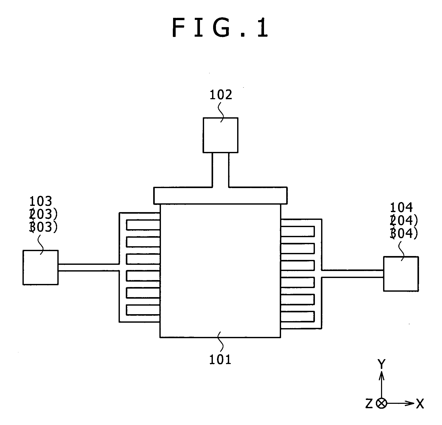
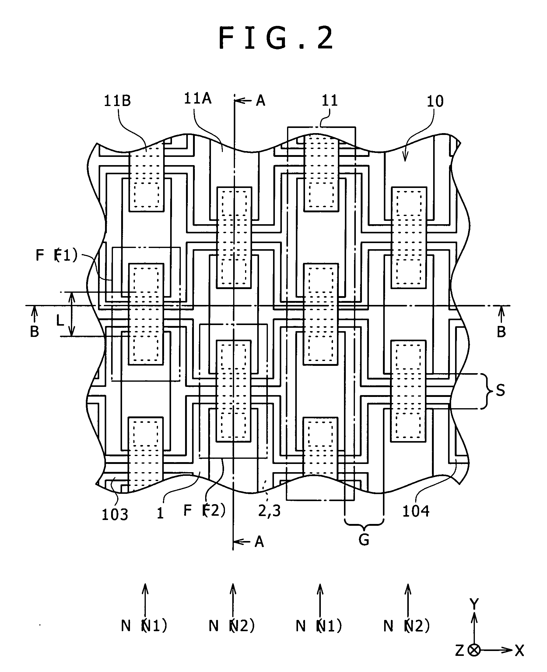
[0054] The structure of a microresonator according to a first embodiment of the invention will be described with reference to FIG. 1. FIG. 1 illustrates the planar structure (planar structure along the XY-plane) of the microresonator.
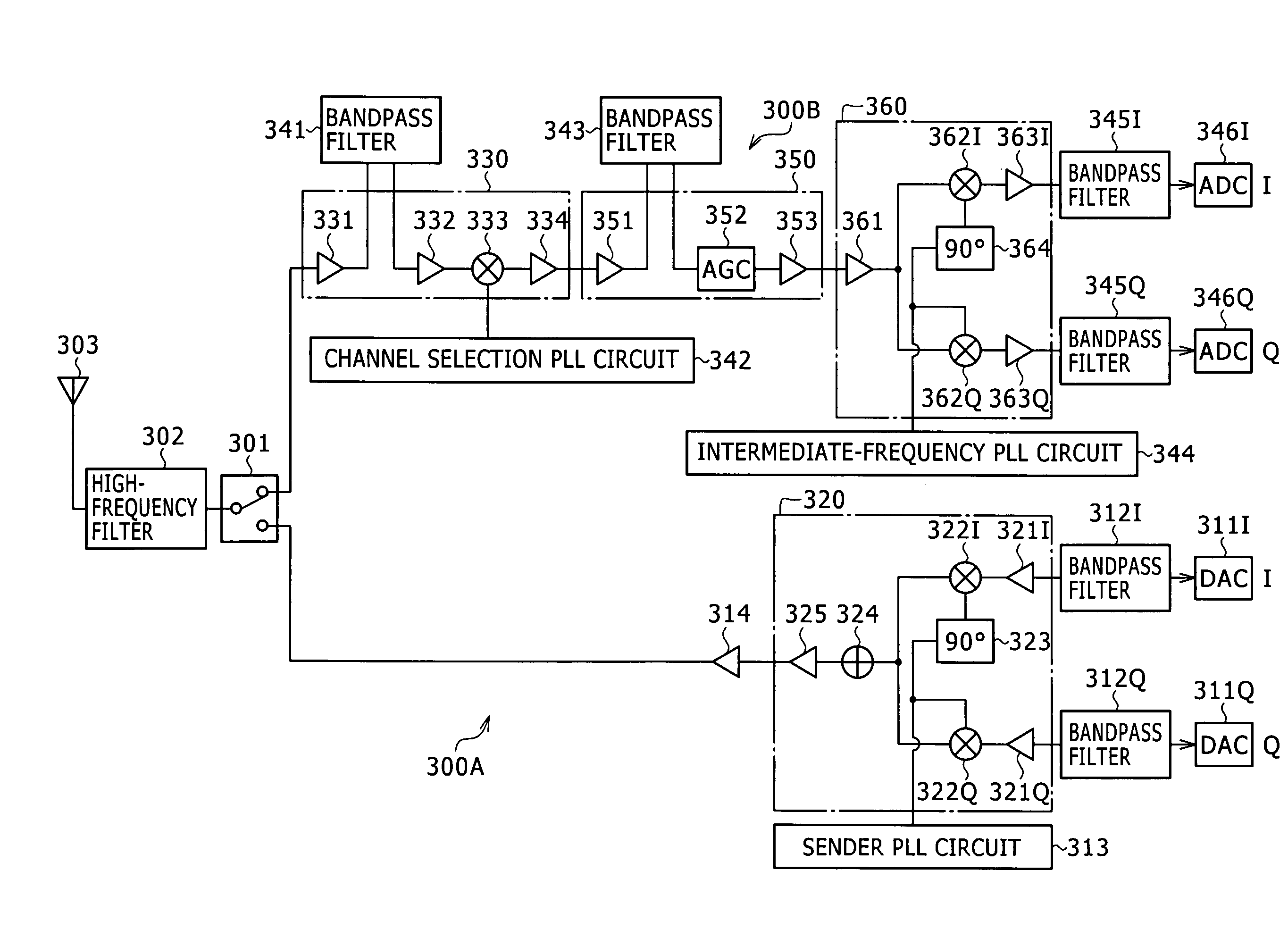
[0055] The microresonator according to the present embodiment is a microstructure (so-called micromachine) used for controlling frequencies for example. Specifically, the microresonator is applied, as a high-frequency filter having a mechanism for controlling frequencies, to an electronic apparatus typified by a communication device such as a cellular phone used in a wireless communication field. Referring to FIG. 1, the microresonator includes a resonant circuit 101 that is an essential part implementing resonant operation, and three electrodes provided for the resonant circuit 101: a DC applying electrode 102 for applying direct current voltages; an input electrode 103 for inputting signals; and an output electrode 104 for outputting signals. Both th...
second embodiment
[0085] A second embodiment according to the invention will be described below.
[0086] Initially, the structure of a microresonator according to a second embodiment of the invention will be described with reference to FIGS. 15 to 17. FIGS. 15 to 17 illustrate the structure of the resonant circuit 101 shown in FIG. 1 in a magnified form. FIG. 15 illustrates the planar structure (planar structure along the XY-plane). FIG. 16 illustrates the sectional structure along the line A-A of FIG. 15 (sectional structure along the YZ-plane). FIG. 17 illustrates the sectional structure along the line B-B of FIG. 15 (sectional structure along the XZ-plane).
[0087] The microresonator according to the present embodiment has almost the same structure as that of the microresonator of the first embodiment (refer to FIGS. 1 to 4), except that the present embodiment includes a microresonator structure 20 instead of the microresonator structure 10, and the microresonator structure 20 includes an input elec...
third embodiment
[0102] A third embodiment according to the invention will be described below.
[0103] Initially, the structure of a microresonator according to a third embodiment of the invention will be described with reference to FIGS. 24 to 26. FIGS. 24 to 26 illustrate the structure of the resonant circuit 101 shown in FIG. 1 in a magnified form. FIG. 24 illustrates the planar structure (planar structure along the XY-plane). FIG. 25 illustrates the sectional structure along the line A-A of FIG. 24 (sectional structure along the XZ-plane). FIG. 26 illustrates the sectional structure along the line B-B of FIG. 24 (sectional structure along the YZ-plane).
[0104] The microresonator according to the present embodiment has almost the same structure as that of the microresonator of the first embodiment (refer to FIGS. 1 to 4), except that the present embodiment includes a microresonator structure 30 instead of the microresonator structure 10, and the microresonator structure 30 includes an input electr...
PUM
 Abstract
Description
Claims
Application Information
 - R&D
- Intellectual Property
- Life Sciences
- Materials
- Tech Scout
- Unparalleled Data Quality
- Higher Quality Content
- 60% Fewer Hallucinations
Browse by: Latest US Patents, China's latest patents, Technical Efficacy Thesaurus, Application Domain, Technology Topic, Popular Technical Reports.
© 2025 PatSnap. All rights reserved.Legal|Privacy policy|Modern Slavery Act Transparency Statement|Sitemap|About US| Contact US: help@patsnap.com


