

Electrical micro-optic module with improved joint structures
a technology of joint structure and micro-optic module, which is applied in the field of electric micro-optic module, can solve the problems of poor conditions of dust particles (either absorbed or moved), performance degradation, and still exist particles, and achieve the effect of improving the effect against esd and better protecting esd
- Summary
- Abstract
- Description
- Claims
- Application Information
AI Technical Summary
Benefits of technology
Problems solved by technology
Method used
Image

Examples
first embodiment
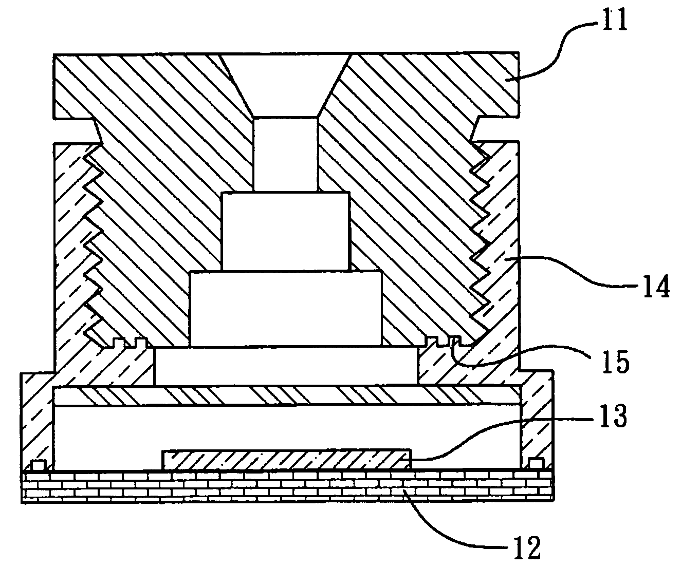
[0020] Referring to FIG. 1, the present invention provides an electrical micro optics module with particle and moisture resistance through a zigzag interface design. The electrical micro optics module comprises: a substrate 12; an image sensor 13 located on the substrate 12; a lens barrel 11 in the shape of a cylinder, comprising an first circumferential surface, a first end surfaces, and a second end surface, wherein a first thread structure is formed on said first circumferential surface and a first zig-zag structure is formed on the second end surface; and a lens mount 14 covering the substrate 12, comprising a holding structure, of which inner walls are formed in an appropriate shape so as to install said lens barrel therein, and said appropriate shape comprising a second circumferential surface and an third surface, wherein a second thread structure is formed on said second circumferential surface and a second zig-zag structure is formed on the third end surface, whereby the fi...
second embodiment
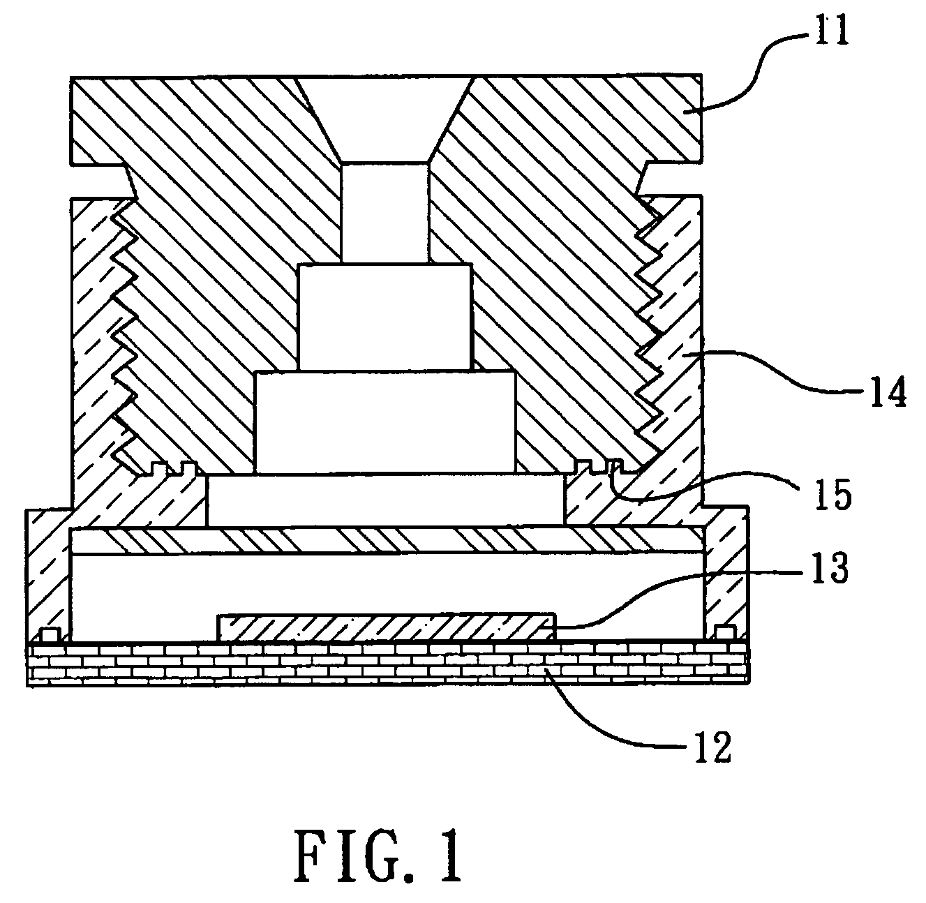
[0021] Referring to FIG. 2, the present invention provides an electrical micro optics module with particle and moisture resistance through tapered thread design with reduced pitch. A typical eMOM contains a substrate 12, an image sensor 13, a lens barrel 11, and a lens mount 14. Tapered thread 21 forces the surfaces of the barrel and the mount to match closer during advancing or tightening. The smaller the clearance between the barrel and the mount, the fewer amounts for particles, moisture or light to pass through the passage. Besides, impact or vibration robustness is improved due to tighter thread coupling and self-lock effect. In the present embodiment, the thread pitch is reduced gradually from outermost side (Object side) to the innermost side (Image side). In the embodiment shown in FIG. 2, a tapered thread 21 with varied pitch is shown. Tapered structure facilitates eccentricity control, too. Reducing pitch enhances the tightening effect abovementioned, in which particle pre...
third embodiment
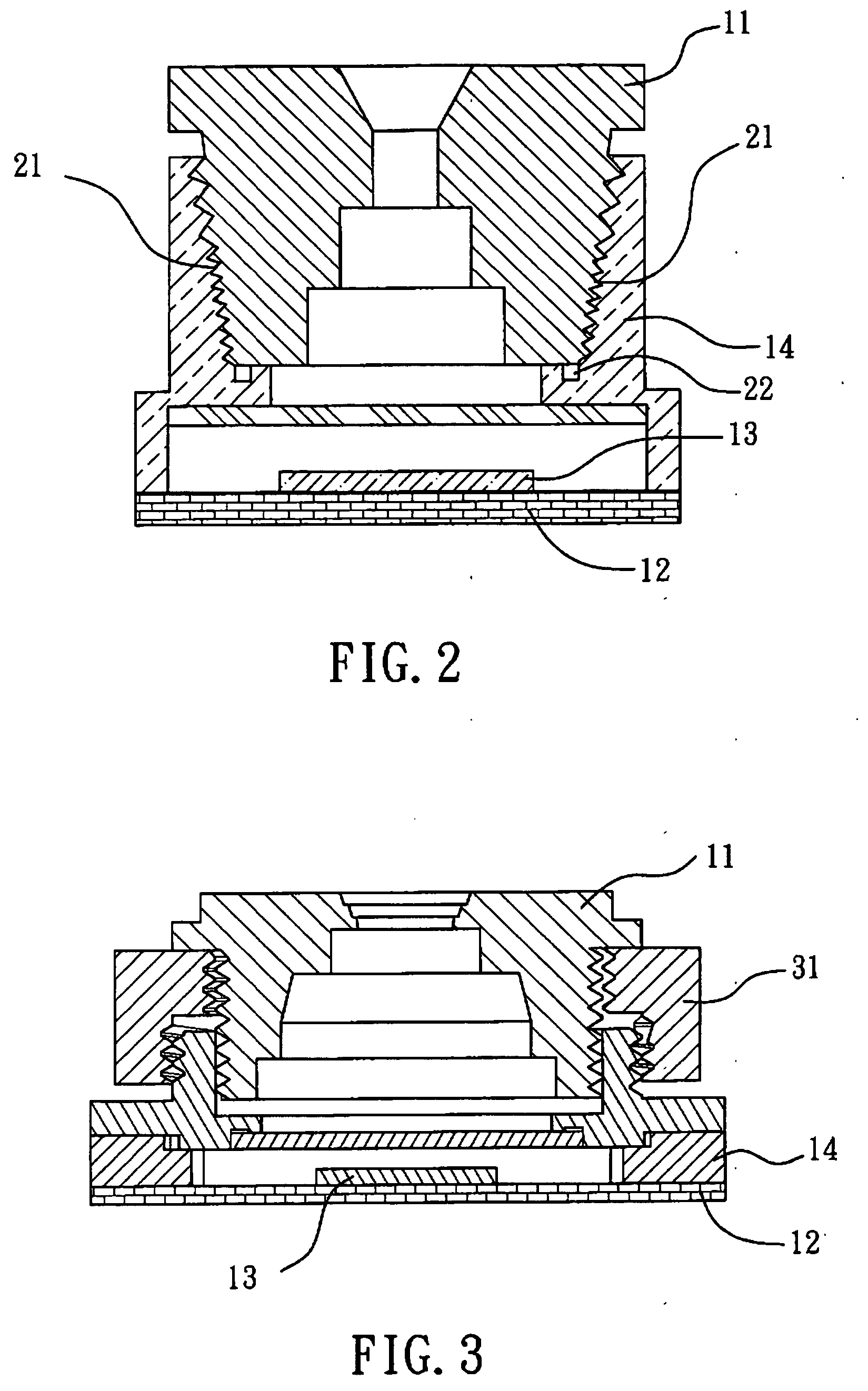
[0022] Referring to FIG. 3, the present invention provides an electrical micro optics module with particle and moisture resistance through an outer thread collar 31 design. A typical eMOM contains a substrate 12, an image sensor 13, a lens barrel 11, and a lens mount 14. As can be seen from the drawing, an outer thread collar 31 facilitates the function of threading and particles generated during threading will drop mostly outside the area of light path by the three-part design of lens mount, lens barrel, and outer thread collar. Elongated moisture and light passage can be expected, too.
PUM
 Abstract
Description
Claims
Application Information