Fiber optic strain sensor and associated data acquisition system

a fiber optic strain sensor and data acquisition technology, applied in the direction of direct mass flowmeters, liquid/fluent solid measurement, volume/mass flow by dynamic fluid flow effect, etc., can solve the problems of manufacturers trying to exploit the fiber optic sensor technology, the cost and complexity of the electronic and optical systems required to implement the fiber optic sensor were prohibitively high for most applications

Inactive Publication Date: 2006-05-18
IVTSENKOV GENNADII
View PDF16 Cites 37 Cited by
  • Summary
  • Abstract
  • Description
  • Claims
  • Application Information

AI Technical Summary

Benefits of technology

[0020] The present invention alleviates the disadvantages of the prior art by utilization of specific stresses applied to the sensitive element—a single mode optic fiber, polarization features of graded-index multimode optic fiber, mechanical transducers transforming measured parameters into specific stress of the optic fiber, and associated all-optical data acquisition system implementing the novel polarization controlling technology for fiber optic lines.

Problems solved by technology

This optical sensor technology has overcome many of the inherent disadvantages of resistance strain gages and its electrical transmission networks, including long-term measurement drift, sensitivity to electromagnetic interference, and dangers from electrical power requirements, which have limited their application in certain fields, such as fire and explosion hazardous environments.
Within the past two decades, a number of manufacturers have attempted to exploit this fiber optic sensor technology, with limited results.
The costs and complexity associated with the electronic and optical systems required to implement the fiber optic sensors were prohibitively high for most applications.
The review of the existed fiber optic strain sensors, its principles and designs reveals that the sensors mentioned above have some disadvantages, such as high cost and complexity of measuring equipment.
In some cases, the data acquisition systems utilizing these sensors have problems with the measurement instability, temperature and polarization sensitivity (especially, interferometer-based sensors).
Also, measuring system implementing fiber optic strain sensors based on Bragg grating technology requires complicated multi-line single mode light source that has to provide large number of spectral lines, or wavelength scanning light source.
It usually appears in conventional single-mode optical fiber and creates serious problems for the newest telecommunication lines using polarization-sensitive equipment.
Generally, a conventional single-mode optical fiber can not maintain polarization of light signal running in the fiber.
In the preferred embodiment of U.S. Pat. No. 4,564,289, the author utilizes an axial stretching of the fiber—the strain that is suitable for the Bragg grating sensors, but does not produce high birefringent effect.
Also, light emitting diode proposed in U.S. Pat. No. 4,564,289 can not be properly matched with single mode fiber, and multi-wavelength light, also proposed there, causes different polarization variation for each wavelength so making measurement less reliable.

Method used


Image

  • Fiber optic strain sensor and associated data acquisition system
  • Fiber optic strain sensor and associated data acquisition system
  • Fiber optic strain sensor and associated data acquisition system

Examples


embodiment

Micro-Force Sensor Embodiment

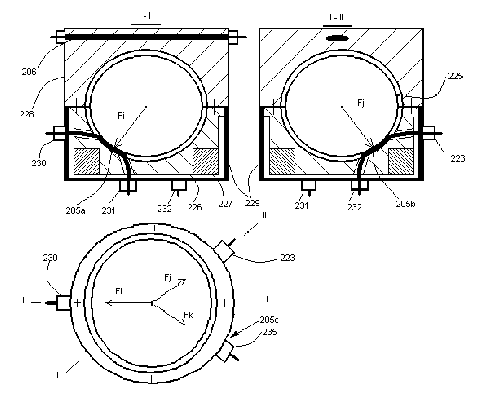
[0055] To sense low forces produced by such phenomena as electric or magnetic field, light pressure and others that scientific laboratories deal with, the invention can be embodied as depicted in FIG. 10. In this embodiment, the measured force is transformed into twisting stress of measuring optical fiber 205. The force perpendicularly applied to plain of blade 292 axially turns fiber 205 until resistance of the fiber stops it. Thus, fiber 205 is twisted proportionally to applied force so changing polarization of the light passing the fiber. The fiber input and output are placed in sealed tubes 293 and 294, and optically coupled to fiber optic connectors 296 and 297. Fiber 205 can be laminated to protect the fiber in aggressive environments.

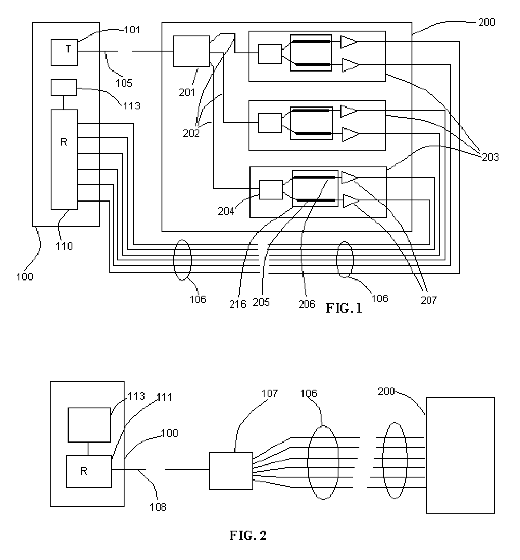
[0056] In all the illustrated embodiments, the photoelastic sensing module is designated by the numeral 200 and electro-optical module is designated by the numeral 100. In all the embodiments, the two fibers are pref...


PUM


Abstract

A fiber optic polarimetric strain sensor and associated data acquisition system capable of all-optical measurements of physical parameters, such as structural strain, gas and liquid pressure, acceleration and vibration, gas and liquid flow rate, and force without fire and explosion hazards associated with conventional strain gage technologies, such as resistance foil strain gages. The polarimetric strain sensor houses a sensitive element—a length of single mode optic fiber—changing polarization of a single-mode optical signal running in the fiber under some mechanical affects, specifically twisting and radial compressing. A linearly-polarized light passes the sensor, which causes polarization deviation of the light, particularly, polarization plane rotation under mentioned above twisting or compressive stresses applied to a sensitive element of the sensor. A multi-channel time division multiplexing data acquisition system that includes polarization analyzer indicates the polarization state deviation caused by the strain, so allow measuring the parameters. The invention may be embodied for measurements of any phenomenon that can be transformed in stress on an optical fiber.

Description

FIELD OF THE INVENTION [0001] The present invention relates to the measurement of physical parameters, such as strain, pressure, acceleration, flow rate and force by fiber optic sensor utilizing the photoelastic effect. More particularly, the invention pertains to utilize in the optic sensor specific strains of single mode and graded-index multimode optical fiber, such as radial compression and twisting, which effectively produce the photoelastic effect. The present invention also relates to associated data acquisition systems. BACKGROUND OF THE INVENTION [0002] This application is the corresponding non-provisional one related to the provisional application No. 60 / 522845 filed Nov. 12, 2004. [0003] Fiber optic sensors successfully substitute now conventional resistance strain gages that have been the most widely used in the past, and are the most readily available technology at this time. The sensitive element of fiber optic sensors is a length of specially prepared optic fiber that...

Claims


Application Information

Patent Timeline
Patent Type & Authority Applications(United States)
IPC IPC(8): G02B6/00
CPCG01F1/206G01F1/28G01F1/80G01H9/004G01L1/243G01D5/35351G01L9/0032G01L9/0039G01P15/093G01P15/18G01D5/344G01L9/0007
Inventor IVTSENKOV, GENNADII
Owner IVTSENKOV GENNADII
Why Eureka
Try Eureka