Feedback control for modulating gas burner

a modulating gas burner and feedback control technology, applied in the direction of combustion regulation, combustion ignition/checking, lighting and heating apparatus, etc., can solve the problem of inability to achieve low-cost gas valves, and achieve the effect of maintaining accuracy

Active Publication Date: 2006-05-18
ADEMCO INC +1
View PDF75 Cites 22 Cited by
  • Summary
  • Abstract
  • Description
  • Claims
  • Application Information

AI Technical Summary

Benefits of technology

[0007] The present invention solves these problems by providing a feedback signal to give an indication of the output level so that the input signal can be adjusted via a closed loop control to achieve the desired output level. In order to detect the output gas flow, we have discovered that the flame ionization signal from a flame sensor, such as mentioned in German Patent P19857238.7 granted Apr. 7, 2000 and that has been used to detect the presence of flame and to provide a shut down of the gas valve if the flame should fail to light or is extinguished after lighting, is also a signal which varies in a predictable fashion with gas flow. By using a predetermined relationship, a controller can monitor the flame ionization level and use it as a feed back signal to adjust the modulation input signal and thus obtain the desired output pressure. However, the flame ionization signal may change with contamination of the flame rod over a period of time so an automatic field calibration should be performed to maintain accuracy.
[0008] Accordingly, the present invention also provides calibration by driving the gas valve with a maximum modulation signal which is guaranteed to open the gas valve to a calibrated high pressure setting. The tolerance of the high pressure setting is easily controlled to a tight range of values. The flame is ignited at the high level and the flame ionization signal is recorded. From this high fire flame ionization level, the system determines the flame ionization levels for other output flows. Thus the appliance can be controlled in a narrower pressure tolerance band than could be obtained without this type of feedback control.
[0009] Like the gas pressure calibration, the airflow also needs to be automatically calibrated. This is required for the proper accuracy of the gas / air mixture at any point in the modulating range. In the present invention, the airflow is modulated by modulating the fan speed of the combustion air blower to be described. The RPM of the fan is supervised through an RPM sensor. The maximum setting airflow is calibrated by increasing the airflow (by increasing the RPM) until the set point of the pressure switch is reached. This point corresponds to the maximum load or 100% airflow. Now the airflow is calibrated. The airflow from this maximum point is proportional to the RPM of the fan at a certain temperature.

Problems solved by technology

This leads to two problems: the first is the production tolerance of the modulating gas valve and the second is the tolerance of the combustion air control system.
For optimal efficiency, this range should be lower and while the range can be lowered by achieving tighter tolerances for the modulating valves in a batch, this is quite impractical for a low cost gas valve.

Method used


Image

  • Feedback control for modulating gas burner
  • Feedback control for modulating gas burner

Examples


Embodiment Construction

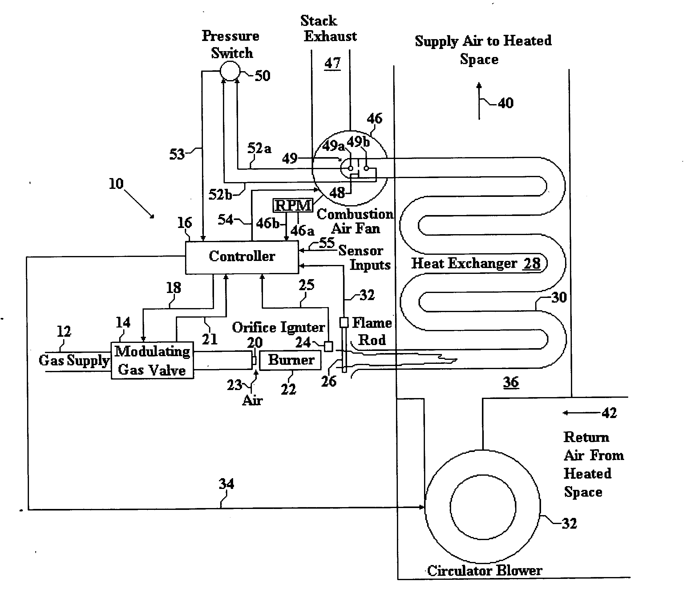
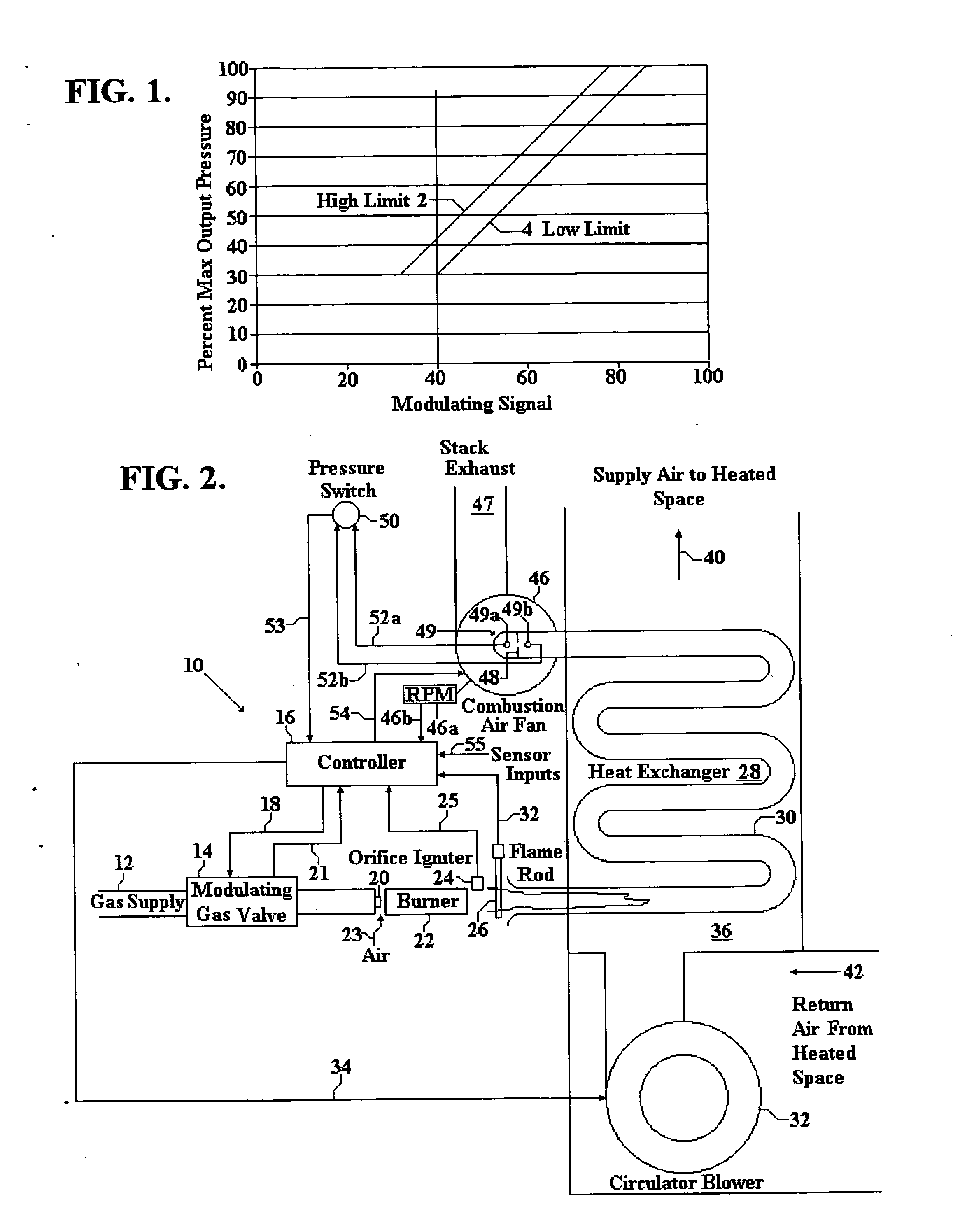
[0012] In FIG. 2, a gas burner control system 10 is shown connected to a gas supply 12 to provide a source of gas to a modulating gas valve 14. A controller 16 is shown providing a modulation signal to gas valve 14 over a connection 18 to control the opening of gas valve 14 and thus control the gas flow through an orifice 20. Gas valve 14 also receives on and off signals from the controller 16 over a connection 21. A burner 22 receives the gas flow from orifice 20 and also receives air from a source shown by arrow 23 and the gas and air become mixed. An igniter 24 that is activated from the controller 16 over a line 25 ignites the gas / air mixture and produces a flame which leaves the burner 22 and is thrown past a flame rod 26 into a heat exchanger 28 shown as a snake-like tube 30. As mentioned, flame rod 26 senses the presence of flame and provides a signal over a line 32 to the controller 16 to shut down the gas valve if the flame should fail to light or is extinguished after ligh...


PUM


Abstract

A modulating gas burner control system using closed loop feedback from a flame rod which provides a signal that varies with gas pressure and which provides combustion air fan control to accurately control the heat from the system without use of expensive control valves.

Description

BACKGROUND OF THE INVENTION [0001] 1. Field of the Invention [0002] The present invention relates to gas burner control and more particularly to feedback control for modulating gas burners. [0003] 2. Description of the Prior Art [0004] Gas burners employ a source of gas which passes through a regulator to control the flow emitted through an orifice. A source of air is mixed with the gas and the gas / air mixture is transmitted to a burner where an igniter causes combustion. The resulting flames are thrown past a flame sensor into a heat exchanger that transfers heat to a supply of air directed to the space to be heated. The flow of burning gas / air mixture in the heat exchanger is controlled by a combustion fan at one end. The gas / air flow is proportional to the RPM of the fan which is typically supervised by an air pressure switch. Changes in fan speed cause changes in the amount of heat exchanged and the heat that is directed to the space to be heated may be controlled. However, as t...

Claims


Application Information

Patent Timeline
Patent Type & Authority Applications(United States)
IPC IPC(8): F23N1/00
CPCF23N1/022F23N5/123F23N2023/10F23N2027/20F23N2033/08F23N2035/16F23N2223/10F23N2227/20F23N2235/16F23N2233/08
Inventor MUNSTERHUIS, SYBRANDUSSTRAND, ROLF L.
Owner ADEMCO INC
Why Eureka
Try Eureka