Transponder subsystem for supporing location awareness in wireless networks

a wireless network and subsystem technology, applied in special services for subscribers, navigation instruments, instruments, etc., can solve the problems of substantial protocol overhead, inability to provide accurate indoor geolocation, application possibilities of additional geolocation functionality, etc., to avoid disadvantages and be easily attached to goods

Inactive Publication Date: 2006-05-18
IBM CORP
View PDF10 Cites 17 Cited by
  • Summary
  • Abstract
  • Description
  • Claims
  • Application Information

AI Technical Summary

Benefits of technology

[0011] In accordance with the present invention, there is provided an apparatus for determining the location of a communication device within a wireless network. The apparatus comprises at least two transponder units for communicating with the communication device when the communication device is situated in a coverage area of the wireless network and a processing unit for deriving the location of the communication device within the coverage area in dependence on information received from the transponder units.
[0012] In accordance with another aspect of the present invention, there is provided a method for determining the location of a communication device within a wireless network. The method comprises the steps of arranging at least two transponder units for communicating with the communication device when the communication device is situated in a coverage area of the wireless network, receiving information from the transponder units, and deriving the location of the communication device within the coverage area in dependence on the received information.
[0013] In general, a separate and autonomous subsystem of transponder units is employed which allows decoupling the conflicting requirements for the physical placement of an access point with optimized desired coverage area, and the placement of location transponder units within the same coverage area for achieving optimum location-sensing results. Received signal strength (RSS) and / or time delay (TD) data from the subsystem of independent stationary location transponder units are gathered and processed for determining the local position of a mobile station or tagged object, i.e. the communication device. In other words, the determination of a mobile station's or tagged object's location can use the acquisition of measurement parameters such as the received signal strength (RSS) and / or time delay (TD) from a wireless frame exchange between the mobile station or tagged object and a set of usually three responding stations with fixed and known position. The location of the mobile station or tagged object can then be estimated or derived from the information.
[0014] The apparatus or method avoids the disadvantages of using access points for location sensing functions.
[0015] The processing unit can be an integral to the communication device, also referred to as station, which has the advantage that then the station itself can determine its position. This might be helpful for a user with a mobile computer as communication device in order to communicate the user's whereabouts.
[0016] The communication device can be a tag or wireless tag device that is easily attachable to goods. The location of the good can then be determined nearly exactly within a building or a defined area.

Problems solved by technology

However, these technologies cannot provide accurate indoor geolocation, which has its own independent market and technical challenges.
Although an obvious choice, using a multitude of AP's as responding stations within the same location range to provide distance estimates to mobile stations has several drawbacks with respect to WLAN infrastructure installation, data throughput performance, as well as cost and application possibilities of the additional geolocation functionality.
There is a conflict between the physical placement of an AP serving one BSS within its coverage range, and the requirement for several stations responding to location sensing (by using additional AP's according to prior art solutions) within the same coverage range.
Furthermore, if AP's within audible range are chosen to operate on the same channel, severe mutual interference will occur which may preclude the introduction of future protocol extensions addressing quality of service (QoS) such as IEEE 802.11e.
It is a disadvantage that prior to communicating with an AP, stations are required to authenticate and associate / reassociate themselves, which requires several frame exchanges between station and AP thus causing substantial protocol overhead.
With additional AP's used for assisting location sensing the protocol overhead becomes even greater.
It is a further disadvantage of the prior art that the stations support the full protocol stack to communicate with the set of AP's.

Method used


Image

  • Transponder subsystem for supporing location awareness in wireless networks
  • Transponder subsystem for supporing location awareness in wireless networks
  • Transponder subsystem for supporing location awareness in wireless networks

Examples


Embodiment Construction

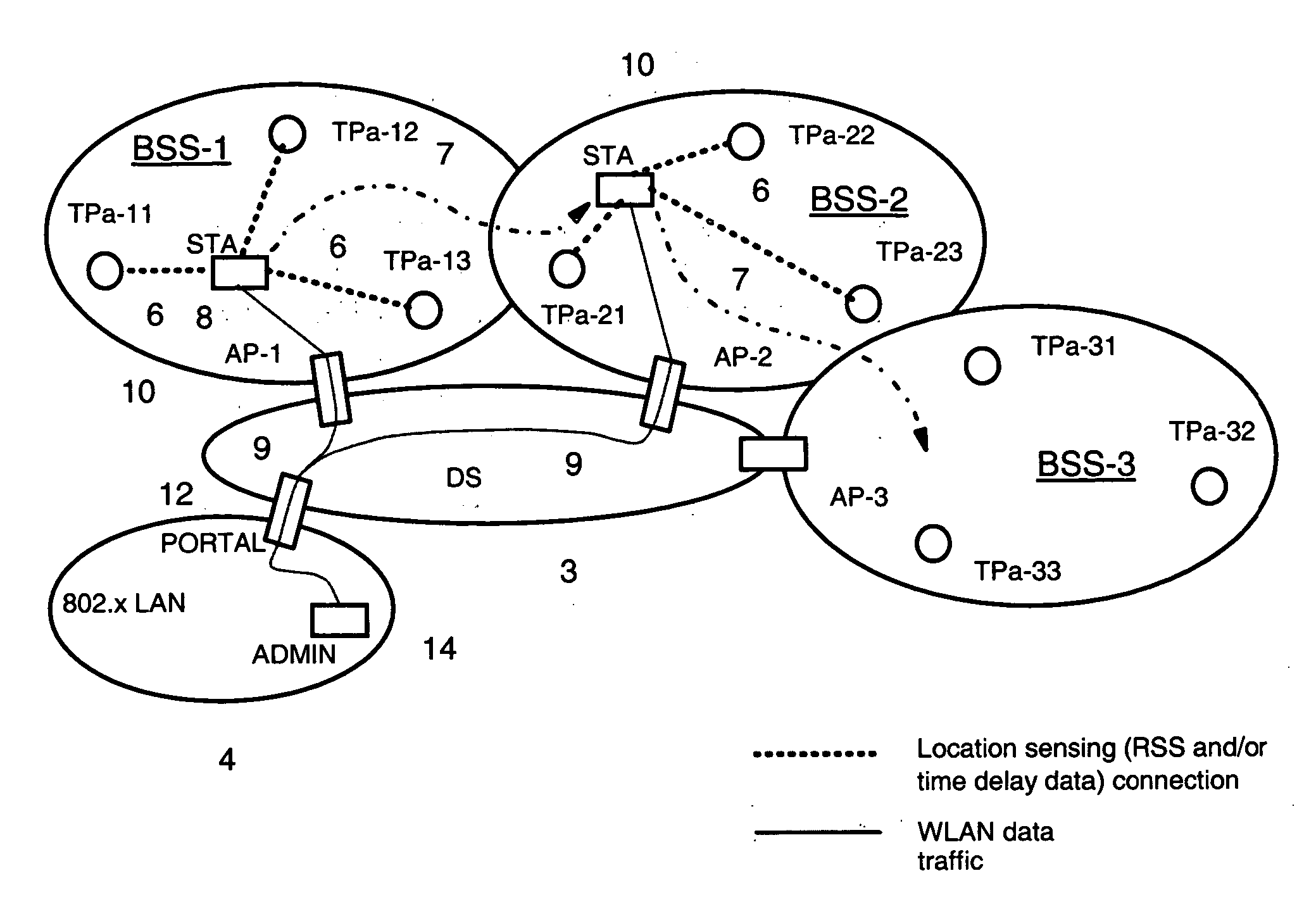
[0052] With reference to FIG. 1, a general layout of a communication environment is described in which a location transponder subsystem for localizing wireless local-area network (WLAN) communication devices can be used. In the figures, same reference signs are used to denote the same or like parts. Before embodiments of the present invention are described, some basics, in accordance with the present invention, are addressed.

[0053] The location of a communication device, i.e. a mobile station or tag, can be determined by using a triangulation method or a signature method.

[0054] The triangulation method is based on the trigonometric calculation of the sought position by taking the estimated line-of-sight propagation distances between mobile station and fixed responding stations into account. The estimated propagation distances can be derived from either line-of-sight propagation time measurements (TD) or from a wireless channel attenuation model estimating the propagation distance ...


PUM


Abstract

The present invention is related to an apparatus and method for determining the location of a communication device within a wireless network in order to provide a geolocation functionality to the communication device participating under an access protocol of a wireless local-area network (WLAN) infrastructure such as IEEE 0.802.11 or Hiperlan. The apparatus comprises at least two transponder units for communicating with the communication device when the communication device is situated in a coverage area of the wireless network and a processing unit for deriving the location of the communication device within the coverage area in dependence on information received from the transponder units.

Description

TECHNICAL FIELD [0001] The present invention is related to an apparatus and method for determining the location of a communication device within a wireless network in order to provide a geolocation functionality to the communication device participating under an access protocol of a wireless local-area network (WLAN) infrastructure such as IEEE 802.11 or Hiperlan. More particularly, the invention allows to determine the location of mobile stations and tagged objects within a coverage area of the wireless network. BACKGROUND OF THE INVENTION [0002] The proliferation of mobile computing devices and wireless local-area networks, also abbreviated to as WLAN's, has created a growing interest in accurate location-aware systems and services. [0003] Of particular interest is the upgrading of existing WLAN infrastructure originally designed for supporting wireless data traffic with a functionality for also enabling location-aware services. The operation (PHY-layer and MAC-layer) of these WLA...

Claims


Application Information

Patent Timeline
Patent Type & Authority Applications(United States)
IPC IPC(8): H04Q7/20G01S19/48H04L12/28H04W64/00
CPCG01C21/206H04W64/00G01S5/0252H04L12/28G01S5/0294
Inventor GFELLER, FRITZHIRT, WALTER
Owner IBM CORP
Why Eureka
Try Eureka