Rotational thrombectomy wire

a thrombus or clot technology, applied in trocar, surgery, medical science, etc., can solve the problems of requiring longer hospital procedures, thrombosis or clots in the graft, vein failure, etc., and achieve the effect of limiting the compressibility of the multifilar wir

Active Publication Date: 2006-05-18
ARGON MEDICAL DEVICES
View PDF99 Cites 54 Cited by
  • Summary
  • Abstract
  • Description
  • Claims
  • Application Information

AI Technical Summary

Benefits of technology

[0012] The present invention provides a rotational thrombectomy wire comprising an inner core composed of a flexible material and a multifilar outer wire surrounding at least a portion of the inner core. The outer wire includes at least first and second metal wires wound side by side and having a sinuous shaped portion at a distal region. The inner core at a distal portion has a sinuous shaped portion within the sinuous portion of the outer wire. The inner core limits the compressibility of the multifilar wire. The multifilar wire is operatively connectable at a proximal end to a motor for rotating the wire to macerate thrombus within the vessel.

Problems solved by technology

(Repeated puncture of the vein could eventually damage the vein and cause blood clots, resulting in vein failure.)
Over a period of time, thrombus or clots may form in the graft.
The disadvantages of these agents are they are expensive, require lengthier hospital procedures and create risks of drug toxicity and bleeding complications as the clots are broken.
This device could be traumatic if used in the vessel, could denude endothelium, create vessel spasms and the basket and drive shaft could fracture.
Although the sinuous wire of the '812 publication is effective in proper clinical use to macerate thrombus in dialysis grafts, it is not suited for use in native vessels.
The device is indicated for use in grafts, and if improperly used the wire can kink or knot, and perhaps even break.
The wire can also bend, making it difficult to withdraw after use, and can lose its shape.
Additionally, the wire would be abrasive to the vessel and the vessel could get caught in the interstices of the wire.
It could also cause vessels spasms which can cause the vessel to squeeze down on the wire which could break the wire.
Similar problems would occur with the use of the device of the '118 patent in native vessels.

Method used


Image

  • Rotational thrombectomy wire
  • Rotational thrombectomy wire
  • Rotational thrombectomy wire

Examples


Embodiment Construction

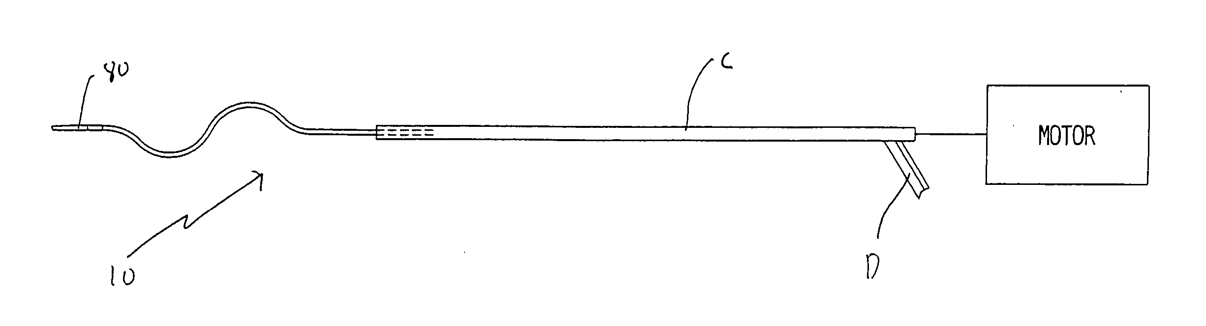
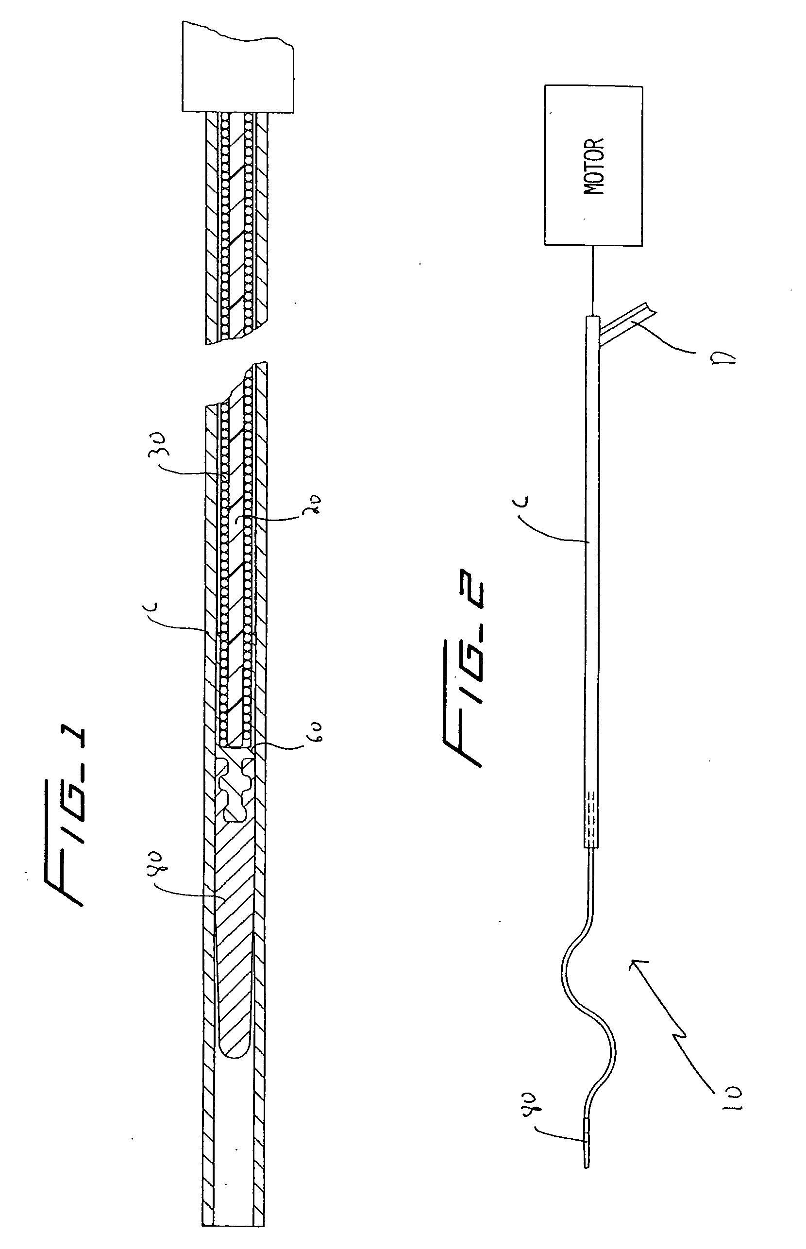
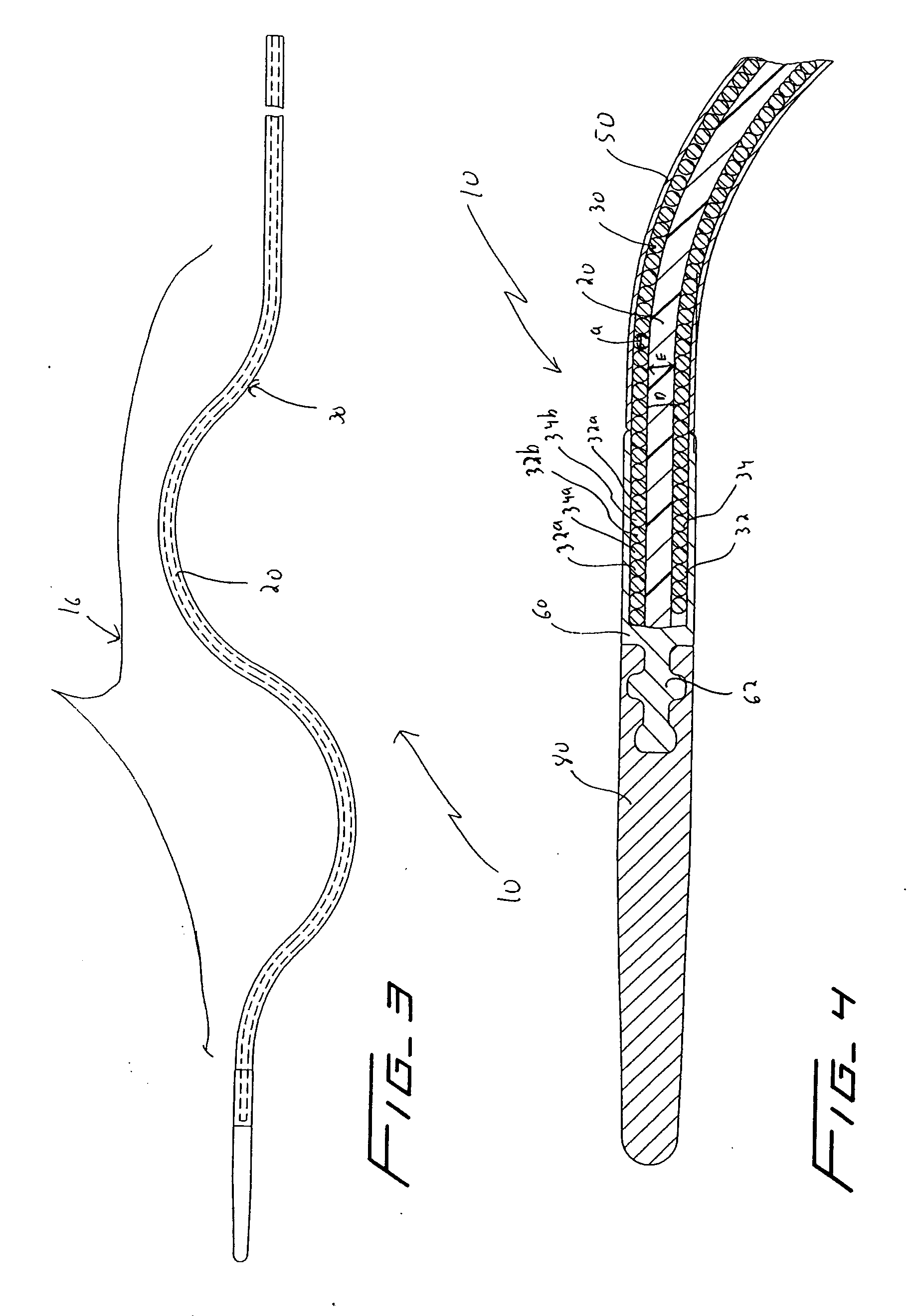
[0036] Referring now in detail to the drawings where like reference numerals identify similar or like components throughout the several views, FIGS. 3 and 4 illustrate a first embodiment of the thrombectomy wire of the present invention. The thrombectomy wire, designated generally by reference numeral 10, includes a core 20, a bifilar wire (coil) 30, and shrink wrap 50. The bifilar wire 30 is formed by two stainless steel wires 32, 34, wound together. As shown they are wound side by side so the cross-sectional area or diameter “a” of the wire fills the space between adjacent turns of the other wire. For example, turns 32a and 32b are filled by respective turns 34a, 34b as shown. Preferably the bifilar wire 30 has a length of about 30 inches and a diameter of about 0.030 inches to about 0.040 inches and more preferably about 0.035 inches. When used in deeper native vessels, e.g. deep veins of the legs or pulmonary circuit, the wire 30 can have a length of about 52 inches. Other dimen...


PUM


Abstract

A rotatable thrombectomy wire for breaking up thrombus or other obstructive material comprising an inner core composed of a flexible material and an outer wire surrounding at least a portion of the inner core. The outer wire has a sinuous shaped portion at a distal region. The inner core limits the compressibility of the outer wire. The outer wire is operatively connectable at a proximal end to a motor for rotating the wire to macerate thrombus.

Description

[0001] This application claims priority from provisional application Ser. No. 60 / 628,623, filed Nov. 17, 2004, the entire contents of which are incorporated herein by reference.BACKGROUND [0002] 1. Technical Field [0003] This application relates to a rotational thrombectomy wire for clearing thrombus from native vessels. [0004] 2. Background of Related Art [0005] In one method of hemodialysis, dialysis grafts, typically of PTFE, are implanted under the patient's skin, e.g. the patient's forearm, and sutured at one end to the vein for outflow and at the other end to the artery for inflow. The graft functions as a shunt creating high blood flow from the artery to the vein and enables access to the patient's blood without having to directly puncture the vein. (Repeated puncture of the vein could eventually damage the vein and cause blood clots, resulting in vein failure.) One needle is inserted into the graft to withdraw blood from the patient for transport to a dialysis machine (kidne...

Claims


Application Information

Patent Timeline
Patent Type & Authority Applications(United States)
IPC IPC(8): A61B17/22
CPCA61B17/320758A61B2017/320733A61B2017/00867A61M2025/09083
Inventor MCGUCKIN, JAMES F. JR.LEEDLE, JOHN D.ANIDHARAN, THANU
Owner ARGON MEDICAL DEVICES
Why Eureka
Try Eureka