Implant material for minimally invasive spinal interbody fusion surgery

a spinal interbody fusion and implant material technology, applied in the field of percutaneous spinal interbody fusion surgery, can solve the problems muscle weakness, and possible bowel and bladder dysfunction, and achieve the effects of reducing the risk of bowel and bladder dysfunction, and reducing the effect of bowel and bladder function

Inactive Publication Date: 2006-05-18
TSOU PAUL M
View PDF33 Cites 68 Cited by
  • Summary
  • Abstract
  • Description
  • Claims
  • Application Information

AI Technical Summary

Problems solved by technology

This can cause severe back pain, leg pain, muscle weakness, and possibly bowel and bladder dysfunction.
Chronic back pain due to disc failure, without dominant extremity symptoms, may also cause chronic functional impairment.
These prior art techniques have typically caused significant access tissue trauma, even when the skin incision was reduced in length.
Another result is the potential for complications accompanying or following the surgery.
Although an improvement over earlier techniques, these prior art devices have several problems.
Significantly, the prior art cylindrically shaped implants do not achieve maximum surface contact with the generally flat surface of the host end plate bed.
Surgical end-plate cutting structurally weakens the end-plate and introduces the risk of metallic fillers settling into the softer vertebral cancellous body.
This prior art method is problematic when used in either its preferred embodiment or any other approach because it has no annular docking mechanism to ensure the safe delivery of the implant from outside of the body to the intervertebral disc space.
The hydrogel needs a jacket for containment and has no effective fixation to the bone end-plate or the annulus.

Method used


Image

  • Implant material for minimally invasive spinal interbody fusion surgery
  • Implant material for minimally invasive spinal interbody fusion surgery
  • Implant material for minimally invasive spinal interbody fusion surgery

Examples


Embodiment Construction

[0033] According to the present invention, there is disclosed an implant device used when performing percutaneous spinal transforaminal endoscopic interbody fusion. In the following description, for the purposes of explanation, specific devices, production details, surgical methods and tools are set forth in order to provide a more thorough understanding of the invention. It will be apparent to those skilled in the art, however, that the present invention may be practiced without these specifically enumerated details and that the preferred embodiment can be modified so as to provide other capabilities. In some instances, well-known structures and methods have not been described in detail so as not to obscure the present invention unnecessarily.

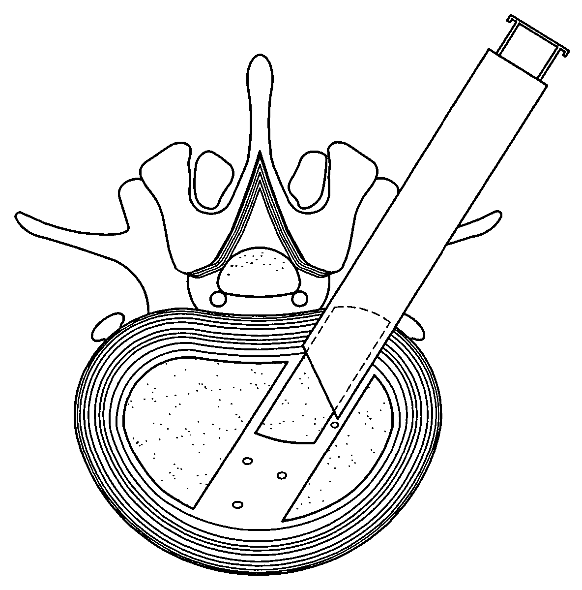
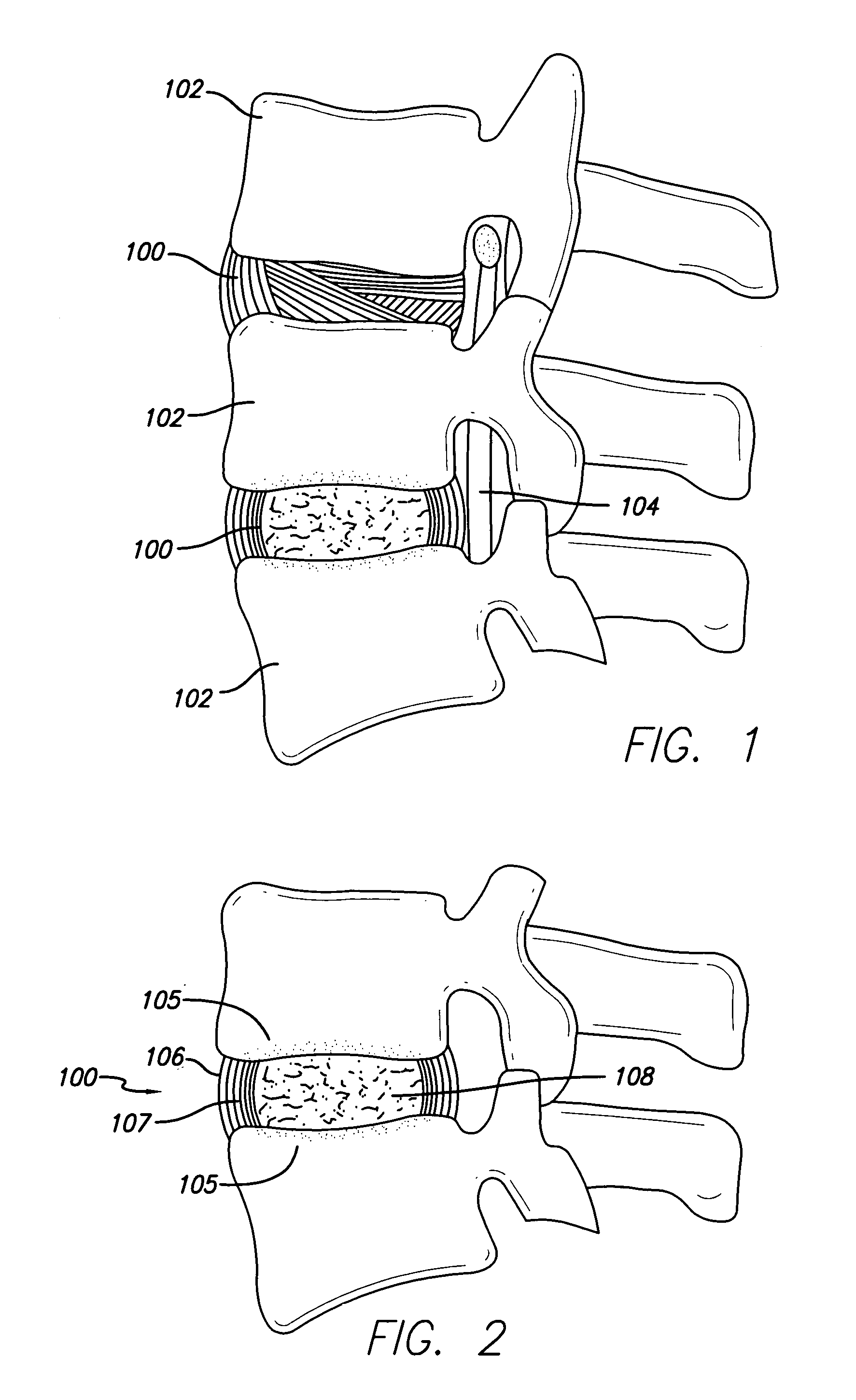
[0034] Referring first to FIG. 1, an idealized side view of a human spinal column illustrating discs located between adjacent vertebrae is shown. A disc 100 is located between each of the adjacent vertebrae 102. The dural sac 104 is shown pas...


PUM

PropertyMeasurementUnit
heightaaaaaaaaaa
shapeaaaaaaaaaa
inertaaaaaaaaaa

Abstract

An implant device for spinal interbody fusion surgery has a shape substantially similar to a human excavated disc space, and includes a first modular end section, at least one modular middle section disposed adjacent to the first modular end section, a second modular end section disposed adjacent to the modular middle section and wherein when the first end section, the middle section and the second end section are placed adjacent to each other, the implant device has a shape with is substantially oval, viewed from top, and a cross section which is bi-convex. The preferred embodiment of the implant device is manufactured from human bone material that has been formed into the shape of the modular components. Alternative embodiments are manufactured from non-human material such as hydrooxyapetite, ceramics, coral and other biodegradable material. Non-resorptable plastic and metal can be used as internal structural members of the implant modules.

Description

BACKGROUND [0001] 1. Field of the Invention [0002] The present invention relates generally to percutaneous spinal interbody fusion surgery and, more specifically, to an implant design and material used to replace spinal nucleus pulposus when performing percutaneous endoscopic transforaminal lumbar and thoracic interbody fusion surgery. [0003] 2. Description of Prior Art [0004] A substantial segment of the population suffers from spinal pain that is caused by degenerative, herniated or protruded intervertebral discs. Intervertebral discs are members of the spinal column that serve as cushions and mobile linkage elements between the adjacent vertebrae. The acute herniation of an intervertebral disc can lead to the compression of spinal nerve elements within the spinal canal and outside of the spinal canal. This can cause severe back pain, leg pain, muscle weakness, and possibly bowel and bladder dysfunction. [0005] Traditional surgical methods to address the problem of spinal nerve el...

Claims


Application Information

Patent Timeline
Patent Type & Authority Applications(United States)
IPC IPC(8): A61F2/44A61B17/68A61B17/86A61F2/00A61F2/02A61F2/28A61F2/30A61F2/46
CPCA61B17/68A61B17/86A61F2/28A61F2/30965A61F2/442A61F2/4465A61F2/4611A61F2002/2835A61F2002/2839A61F2002/30062A61F2002/30125A61F2002/30153A61F2002/30187A61F2002/30324A61F2002/3038A61F2002/30383A61F2002/30599A61F2002/30604A61F2002/30616A61F2002/30795A61F2002/30975A61F2002/444A61F2002/4485A61F2002/4627A61F2002/4629A61F2002/4635A61F2002/4649A61F2210/0004A61F2220/0025A61F2220/0033A61F2230/0008A61F2230/0019A61F2230/0034A61F2250/0036A61F2250/0063A61F2310/00179A61F2310/00293A61F2310/00341A61F2310/00359A61F2002/30331
Inventor TSOU, PAUL M.
Owner TSOU PAUL M
Why Eureka
Try Eureka