Power tool control system

a control system and power tool technology, applied in the field of power tools, can solve the problems of difficulty in using such technology, limited precision and accuracy of the work performed on these power tools, and difficulty in the use of such technology by the equipment operator, and achieve the effect of easy readable format and high quality

Inactive Publication Date: 2006-05-18
CHANG TYPE INDAL
View PDF99 Cites 44 Cited by
  • Summary
  • Abstract
  • Description
  • Claims
  • Application Information

AI Technical Summary

Benefits of technology

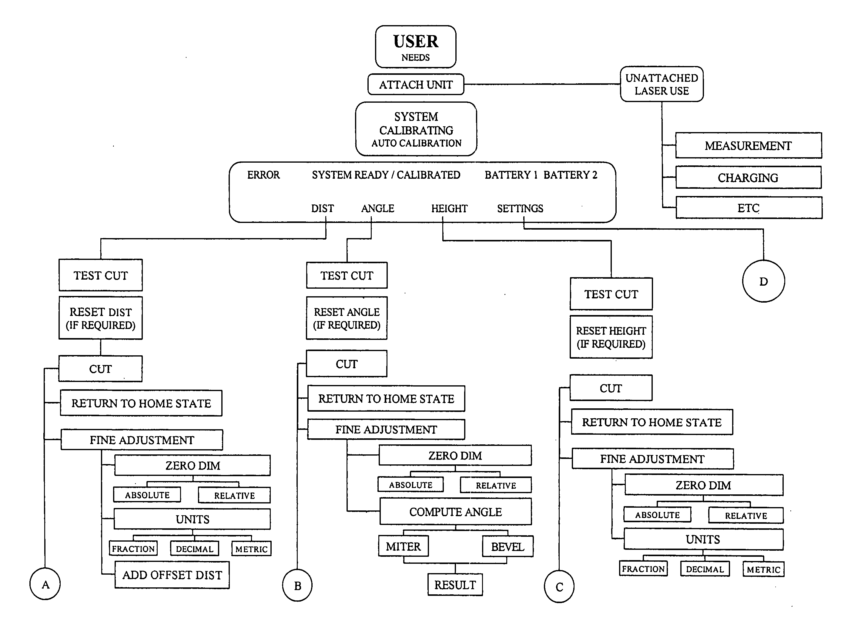
[0007] Accordingly, the present invention is a power tool control system that enables a user to operate a power tool through a graphical user interface communicatively coupled with a non-contact measurement and alignment device. The graphical user interface correlates user engageable select...

Problems solved by technology

Unfortunately, the precision and accuracy of work performed on these power tools is limited by human error and sub-standard equipment.
Even when equipment with the latest advances, such as laser guidance technology, is employed it is often the case that the use of such technology is difficult for the equipment operator.
The difficulties experienced by an operator may be due to a variety of reasons, such as inadequate instructional aids available from the manufacturer or dealer, overly complex operational requirements, or a poorly designed and organized user interface.
Such difficulties have rendered many valuable advances in tool technology unpopular or obsolete due to operator dissatisfaction and frustration.
However, the operator is still required to establish the location of operation and this may result in imprecise and inaccurate work piece production due to imprecise measurements and settings established by the operator.
Consequently, the operator is forced to establish and then re-establish settings, which may lead t...

Method used


Image

  • Power tool control system
  • Power tool control system
  • Power tool control system

Examples


Embodiment Construction

[0166] Reference will now be made in detail to the presently preferred embodiments of the invention, examples of which are illustrated in the accompanying drawings.

[0167] Referring generally now to FIGS. 1 through 142, exemplary embodiments of the present invention are shown.

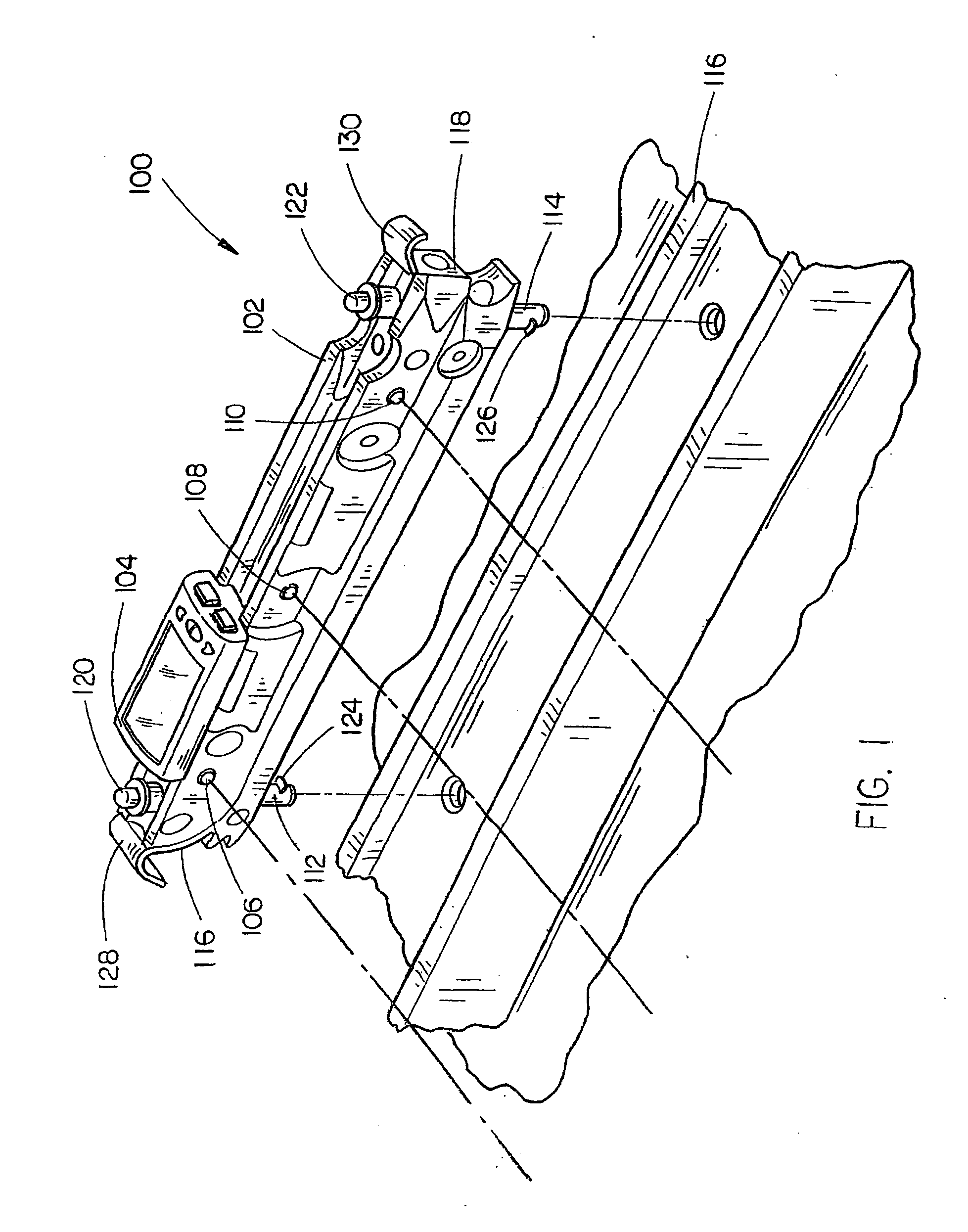
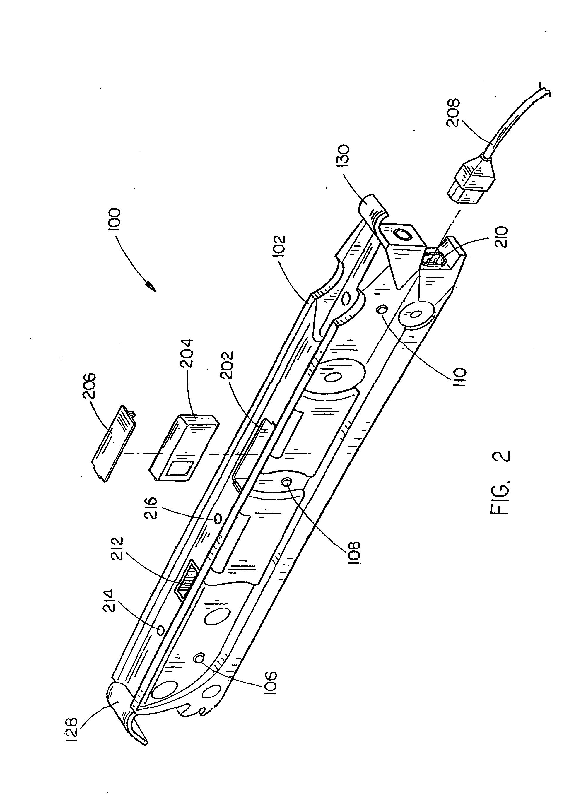
[0168] Referring generally now to FIG. 1, a laser apparatus 100 of the present invention is shown. In the present embodiment, the laser apparatus 100 comprises a housing 102 coupled with a computing system 104. Further, the housing 102 is disposed with an optical assembly including a first laser source 106, a second laser source 108, and a third laser source 110, in the preferred embodiment. Alternatively, the housing 102 may include a greater or fewer number of laser sources in order to meet the needs of a manufacturer or consumer. Each of the three laser sources 106 through 110 is in communication with the computing system 104. In the current embodiment the communicative link is a wireless system, however, a...


PUM

PropertyMeasurementUnit
Angleaaaaaaaaaa

Abstract

A power tool control system includes a non-contact measurement and alignment device operative with the power tool and enabled to establish various readings, such as power tool settings. A graphical user interface communicatively coupled with the non-contact measurement and alignment device enables user control over and display of the readings from the non-contact measurement and alignment device.

Description

CROSS REFERENCE TO RELATED APPLICATIONS [0001] The present invention is a continuation-in-part of U.S. application Ser. No. 10 / 632,559, filed on Jul. 31, 2003, which is a continuation of U.S. application Ser. No. 10 / 463,206, filed on Jun. 16, 2003 which is a continuation-in-part of U.S. application Ser. No. 10 / 445,290, filed on May 21, 2003, which claimed priority under 35 U.S.C. §119 to U.S. Provisional Application Ser. No. 60 / 429,840, filed on Nov. 27, 2002, and U.S. application Ser. No. 10 / 413,455, filed on Apr. 14, 2003 which claimed priority under 35 U.S.C. §119 to U.S. Provisional Application 60 / 414,200, filed on Sep. 27, 2002 and U.S. Provisional Application 60 / 373,752, filed on Apr. 18, 2002. The U.S. applications, Ser. Nos. 10 / 632,559, 10 / 463,206, 10 / 445,290, 60 / 429,840, 10 / 413,455, 60 / 414,200, and 60 / 373,752, are herein incorporated by reference in their entireties.FIELD OF THE INVENTION [0002] The present invention generally relates to the field of power tools, and partic...

Claims


Application Information

Patent Timeline
IPC IPC(8): G06F19/00
CPCB23B25/06B23B49/00B23B2260/092B23D59/002B23D59/008B23Q17/24B24B49/12B25C7/00B25F5/00B27B27/02B27B27/06G01C15/002Y10T83/849Y10T83/7705
Inventor ETTER, MARK A.GARCIA, JAIME E.DEKEYSER, KATHYPHILLIPS, ALANBURKHOLDER, ROBERT F.WESTON, JEFFREY D.HEARN, MELINDA J.
Owner CHANG TYPE INDAL
Why Eureka
Try Eureka