
Apparatus and method for clarifying exhaust gas of diesel engine

Inactive Publication Date: 2006-05-25
HITACHI LTD
View PDF8 Cites 34 Cited by
  • Summary
  • Abstract
  • Description
  • Claims
  • Application Information

AI Technical Summary

Benefits of technology

[0016] The exhaust gas purifying apparatus for the diesel engine according to the present invention further allows an oxidation catalyst to be arranged on the downstream side of the diesel particulate filter viewed from a flow of the exhaust gas.
[0020] The exhaust gas purifying apparatus for the diesel engine according to the present invention supplies fuel that is a reducing agent necessary for reducing NOx to an exhaust gas by increasing the amount of fuel supplied to the diesel engine.
[0023] The exhaust gas purifying apparatus for the diesel engine according to the present invention allows an NOx catalyst and a diesel particulate filter to be installed sequentially from the upstream side of a flow of an exhaust gas, and to use an NOx adsorption and reduction type catalyst as the NOx catalyst. Therefore, as compared with the NOx occlusion and reduction type catalyst, the speed of reduction of the captured NO2 is fast, and the time when a stoichiometric-rich atmosphere is retained can be shortened to several seconds to several minutes.

Problems solved by technology

However, as the engine load increases, the PM is exposed to a high temperature exhaust gas.
Because an occlusion type NOx catalyst is absorbed (occluded) in an NOx absorbent, the rate of reduction of captured NOx is slow, and the amount of consumption of a reducing agent is large.
For this reason, the occlusion type NOx catalyst requires a long retention time of the reducing atmosphere in which much fuel is required, and is inferior in fuel economy.
Moreover, the occlusion type NOx catalyst is hard to be satisfactory also with regard to durability.

Method used


Image

  • Apparatus and method for clarifying exhaust gas of diesel engine
  • Apparatus and method for clarifying exhaust gas of diesel engine
  • Apparatus and method for clarifying exhaust gas of diesel engine

Examples


Embodiment Construction

[0035] Ideal embodiments according to the present invention are described with reference to appended drawings.

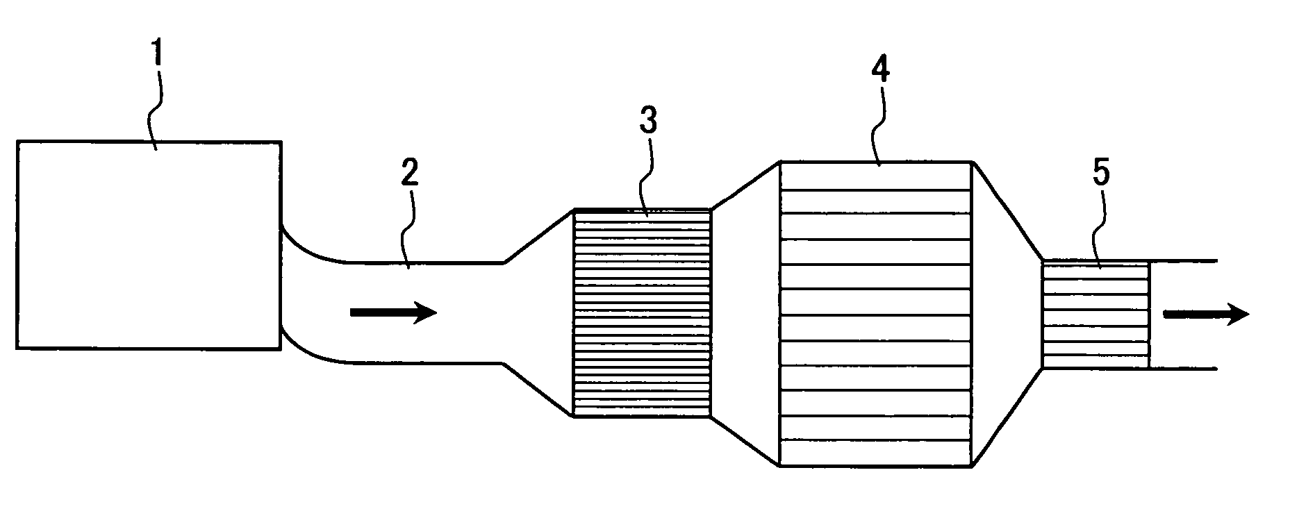
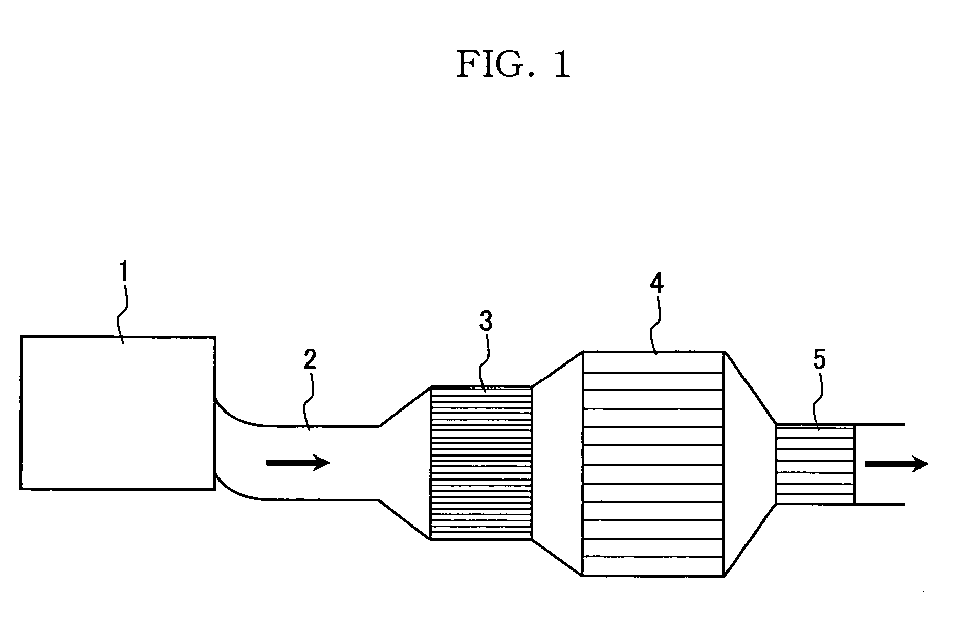
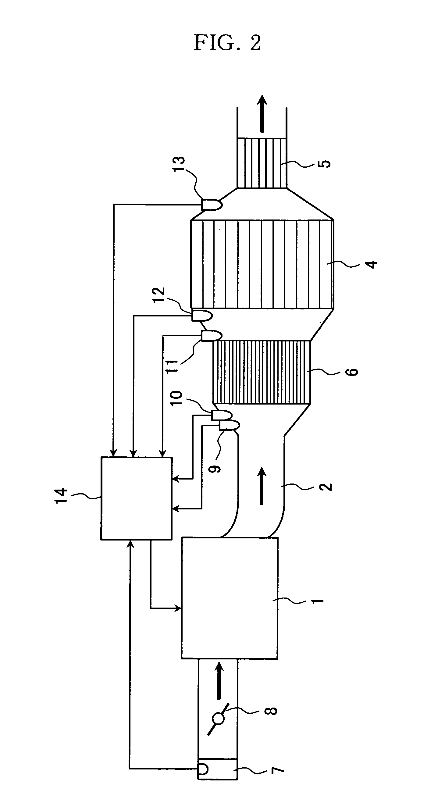
[0036]FIG. 1 shows an outline of an exhaust gas purifying apparatus for a diesel engine according to the present invention. An exhaust gas exhausted from a diesel engine 1 is purified by an NOx purification catalyst 3, a diesel particulate filter (hereinafter referred to as a DPF) 4, and an oxidation catalyst 5 in the process of an exhaust gas channel 2, that is, of passing through an exhaust pipe.

[0037] Because the present invention allows the NOx purification catalyst 3 to be arranged on the upstream side of a flow of an exhaust gas than the DPF 4 or the oxidation catalyst 5 toward the flow of the exhaust gas, and because a catalyst temperature is easy to rise, and the precise control of temperature and an atmosphere is enabled, sufficient NOx purification performance can be obtained.

[0038] Changing an exhaust gas into a reducing atmosphere is enabled by using a fuel se...


PUM

PropertyMeasurementUnit
Temperatureaaaaaaaaaa
Flow rateaaaaaaaaaa

Abstract

An apparatus for purifying an exhaust gas of a diesel engine, characterized in that it has an NOx adsorption and reduction type catalyst and a diesel particulate filter for oxidizing and removing particulate matters in the exhaust gas, which are provided in the flow route for the exhaust gas and are arranged in the above described order from the upstream of the flow of the exhaust gas. The above arrangement allows the elevation of the temperature of the catalyst with ease and the precise control of the temperature and atmosphere therein, resulting in the achievement of satisfactory NOx purification performance, and the employment of the NOx adsorption and reduction type catalyst allows the enhancement of the rate of reduction of the NO2 captured, which shortens the time to keep a stoichiometric-rich atmosphere to a time of several seconds to several minutes.

Description

TECHNICAL FIELD [0001] The present invention relates to an apparatus and a method for purifying (clarifying) an exhaust gas of a diesel engine, and, more particularly, relates to an exhaust gas purifying apparatus and an exhaust gas purifying method that are used in vehicles such as automobiles, and purify an exhaust gas exhausted from the diesel engine for the purpose of preventing air pollution. BACKGROUND ART [0002] Nowadays, exhaust gas components, such as nitrogen oxides (NOx), particulate matters (PM), hydrocarbon (HC), and carbon monoxide (CO), are subject to the exhaust emission control of a diesel engine. [0003] Main components of the PM are soot, that is, carbon (C), hydrocarbon, soluble organic fraction (SOF), and sulfur content. However, as the engine load increases, the PM is exposed to a high temperature exhaust gas. Consequently, the hydrocarbon or the SOF vaporizes, and the carbon will occupy most of the PM components. For this reason, the PM stands for the carbon (C...

Claims


Application Information

Patent Timeline
IPC IPC(8): F01N3/00B01D53/34B01D53/94F01N3/02F01N3/023F01N3/027F01N3/035F01N3/08F01N3/10F01N3/24F01N3/28F01N9/00F01N13/02F02D41/02F02D41/14F02D41/30F02D41/38
CPCF01N3/027F01N3/0814F01N3/0821F01N3/0835F01N3/0842F01N3/103F01N9/002F01N2240/16F01N2250/02F01N2250/12F01N2250/14F01N2430/06F01N2430/085F01N2570/14F02D41/0245F02D41/0275F02D41/029F02D41/1441F02D41/1446F02D41/1454F02D41/187F02D41/3011F02D2041/0067F02D2200/0802F02D2200/0806F02D2200/0812Y02T10/26Y02T10/47Y02T10/24F01N13/009F01N13/0097Y02T10/12Y02T10/40Y02A50/20
Inventor KAMIKAWA, MASAYUKIIIZUKA, HIDEHIROKANEEDA, MASATOHIGASHIYAMA, KAZUTOSHIKITAHARA, YUICHIKURODA, OSAMU
Owner HITACHI LTD
Learn More