Method of determining in real time the flow rate characteristic of a fuel injector

a fuel injector and flow rate technology, applied in position/direction control, relative volume flow measurement, liquid/fluent solid measurement, etc., can solve the problems of not being able to calculate individualized corrections, richness control not enabling the characteristics of each of the components concerned, etc., and achieve better knowledge of the flow rate characteristic

Active Publication Date: 2006-05-25
MAGNETI MARELLI MOTOPROPULSION FRANCE
View PDF6 Cites 43 Cited by
  • Summary
  • Abstract
  • Description
  • Claims
  • Application Information

AI Technical Summary

Benefits of technology

[0009] The object of the invention is thus to obtain better knowledge of the flow rate characteristic of at least one injector of an engine in operation by determining in real time the offset of the injector in question assuming that its gain is known, and also by determining the non-linear portion of its characteristic in order to be able to track variations in the individual flow rate characteristics of each of the injectors, and also to be able to track variation in the global characteristic of the injectors of an engine, taken as a whole.

Problems solved by technology

However, unless using special strategies, closed loop richness control does not enable the characteristics of each of the components concerned to be identified whether individually or globally.
In other words, the measuring out of the air-fuel mixture consists in controlling the rate at which air is admitted to the engine together with a corresponding fuel flow rate, with the closed loop richness control serving to compensate the ratio between the air flow rate and the fuel flow rate, but without identifying which part of the correction should be applied to the air flow rate or to the fuel flow rate, and in addition, richness control does not make it possible to calculate an individualized correction for each cylinder, and thus for each injector.

Method used


Image

  • Method of determining in real time the flow rate characteristic of a fuel injector
  • Method of determining in real time the flow rate characteristic of a fuel injector
  • Method of determining in real time the flow rate characteristic of a fuel injector

Examples


Embodiment Construction

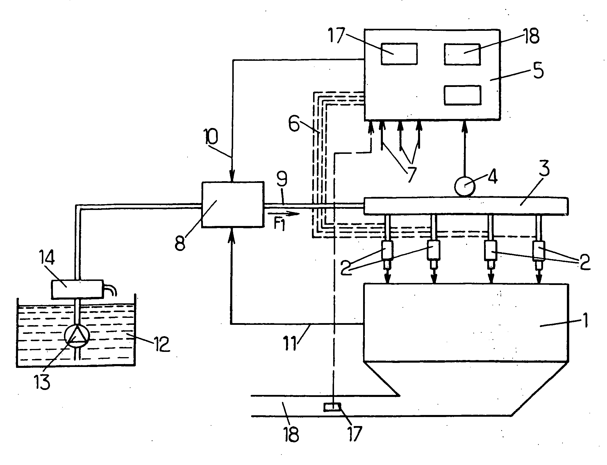
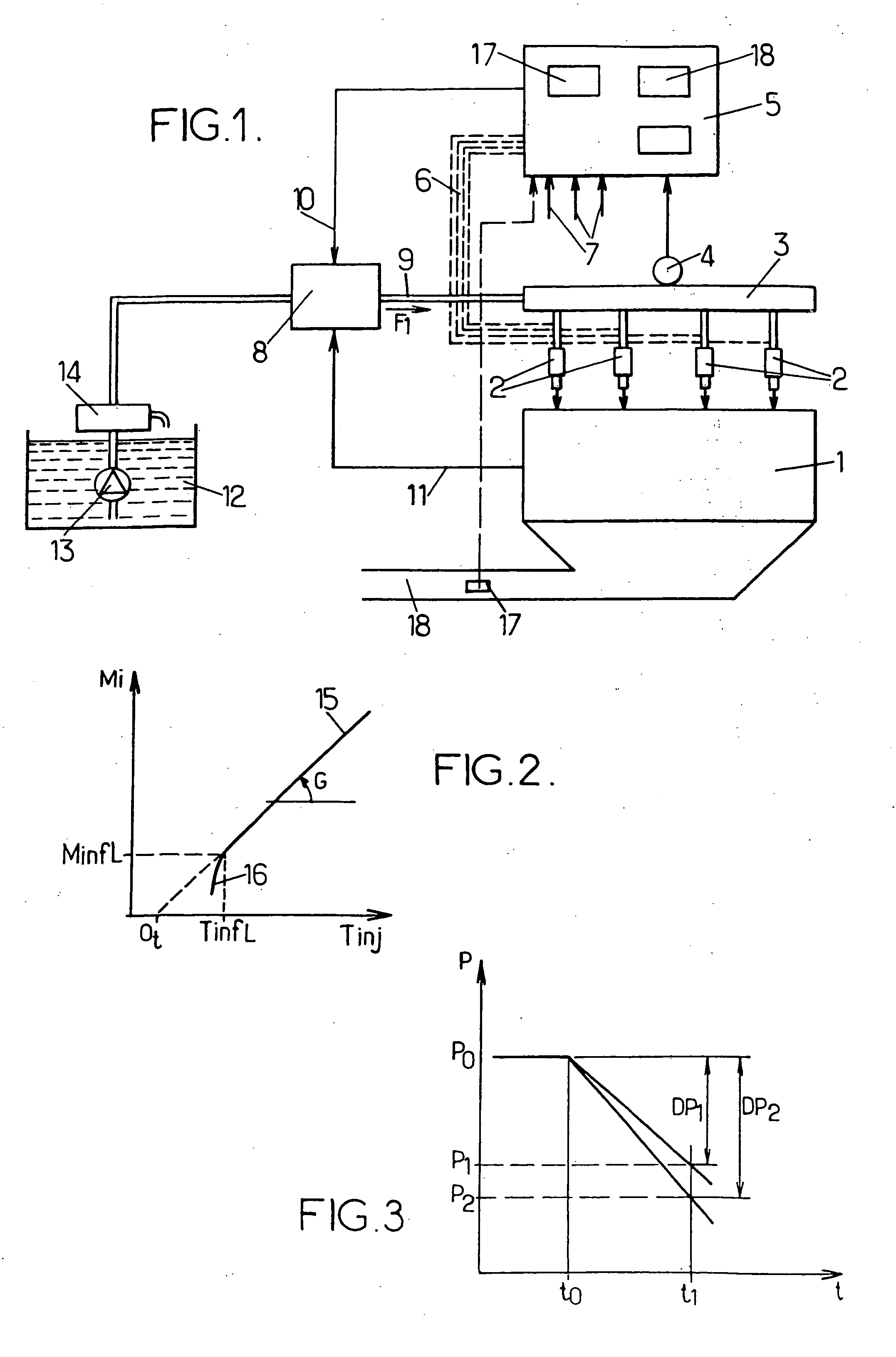
[0036]FIG. 1 is a diagram showing an internal combustion engine 1 of a motor vehicle. By way of example, the engine in question 1 is an engine having four cylinders in line with controlled ignition and a four-stroke engine cycle, being fed with fuel by so-called “direct” injection, even though the method of the invention is applicable to an engine using indirect injection and / or to a diesel type engine.

[0037] The fuel is injected into each cylinder of the engine 1 via a respective one of four injectors 2.

[0038] These injectors 2 are fed with fuel at high pressure by a common fuel rail 3 in which the fuel pressure is determined, at least at certain instants of the engine cycle, by a pressure sensor 4 making a measurement and transmitting a measured pressure signal to an engine control unit 5, or by said unit 5 performing calculations on the basis of certain measurements made by the sensor 4 at various instants in the engine cycle, as proposed in French patent No. 2 803 875.

[0039] ...


PUM


Abstract

The method comprises the steps consisting in assuming that the gain of at least one injector is equal to a theoretical gain or an updated gain, and in replacing each of at least one reference injection of injection control duration controlled by the engine control unit in application of a stored characteristic, with a multiple injection comprising a succession of at least two injections of injection control durations that are assumed to cause the same mass of fuel to be injected as by the replaced reference injection, in determining the fuel mass difference between the reference injection and the multiple injection, in deducing therefrom an error in determining the characteristic, and in modifying the gain and/or the offset of the linear zone of the initial characteristic or at least a table or mathematical relationship for the non-linear zone of said characteristic, so as to compensate the error, and storing the new characteristic as determined in this way. Applications to real time determination as a function of the injection control duration of the flow rate characteristic of fuel injectors for internal combustion engines fed by injection.

Description

[0001] The invention relates to a method of determining the flow rate characteristic of at least one electrically-controlled fuel injector feeding an internal combustion engine and mounted in a fuel feed circuit of the engine, the determination being in real time and as a function of an injection control duration, and said circuit comprising at least one pump fed from a fuel tank and connected to a common rail for feeding fuel to the injectors of the engine, each injector being controlled by an engine control unit, itself including at least one calculator and at least one memory, generally implemented in the form of an electronic engine control unit, such that on each cycle of the engine, each injector delivers a mass of fuel to the engine as determined by said injector flow rate characteristic, which expresses the mass injected as an increasing function of the injection control duration of said injector as controlled by said engine control unit, said unit being capable also of taki...

Claims


Application Information

Patent Timeline
Patent Type & Authority Applications(United States)
IPC IPC(8): F02D41/00G01M15/00F02B77/08F02D41/20F02D41/24F02D41/34F02D41/38F02D41/40F02M63/02F02M65/00
CPCF02D41/20F02D41/2438F02D41/247F02D41/3809F02D41/402F02D2250/12F02D2250/31Y02T10/44Y02T10/40
Inventor MAZET, HENRI
Owner MAGNETI MARELLI MOTOPROPULSION FRANCE
Why Eureka
Try Eureka