
Color cathode ray tube and electron gun used therein

a cathode ray tube and electron gun technology, which is applied in the direction of cathode ray tubes/electron beam tubes, electric discharge tubes, electrical apparatus, etc., can solve the problem of coma aberration in the horizontal direction of side beams, the influence of the potential of the inner wall of the neck cannot be ignored, and the aperture of the main lens is difficult to substantially increase, so as to achieve the effect of enhancing the focus characteristics and reducing the dimension of the beam

Inactive Publication Date: 2006-05-25
MATSUSHITA TOSHIBA PICTURE DISPLAY CO LTD
View PDF5 Cites 2 Cited by
  • Summary
  • Abstract
  • Description
  • Claims
  • Application Information

AI Technical Summary

Benefits of technology

"The present invention provides an electron gun with a main lens that can reduce coma aberration and degradation of convergence, while decreasing the beam spot on the phosphor screen. Additionally, the invention enhances the focus characteristics of a color cathode ray tube without compromising its convergence characteristics. The electron gun includes a focusing electrode and a final-stage accelerating electrode with an electric field correcting electrode for accelerating and focusing the three electron beams. The final-stage accelerating electrode also includes an electric field correcting electrode and a peripheral electrode with a common electron beam passage aperture. The distance between the final-stage accelerating electrode and the electric field correcting electrode in the focusing electrode is smaller than the distance between the final-stage accelerating electrode and the electric field correcting electrode in the final-stage accelerating electrode. The color cathode ray tube includes the electron gun with the main lens."

Problems solved by technology

However, in the case where the interelectrode distance L is enlarged, the influence of the potential of a neck inner wall cannot be ignored.
Thus, it is difficult to enlarge the aperture of the main lens substantially.
However, in the above-mentioned electric field superimposing type main lens, there is a problem that a coma aberration in the horizontal direction occurs in side beams due to the influence of the peripheral electrodes 33, 34.
When the electron beams strike the electrode, the electric potential becomes unstable, and a discharge as well as focus degradation are caused, which may cause the breakdown of a TV set.
However, at this time, as shown in FIG. 21, the distance A between the center beam center path 63 and the side beam center path 60 in the center portion of the phosphor screen becomes about 10 mm, which makes it difficult to correct convergence.
As described above, according to the procedure of III, there is a problem that the reduction in a coma aberration and the securing of convergence cannot be achieved together.
When an attempt is made so as to eliminate this coma aberration, various new problems occur as described above.
Thus, practically, the aperture of a lens cannot be enlarged sufficiently.
Therefore, if the aperture of a lens cannot be enlarged, it is difficult to shorten the dimension of a beam spot on the phosphor screen, and as a result, it is difficult to enhance the resolution of a color cathode ray tube.

Method used


Image

  • Color cathode ray tube and electron gun used therein
  • Color cathode ray tube and electron gun used therein
  • Color cathode ray tube and electron gun used therein

Examples


Embodiment Construction

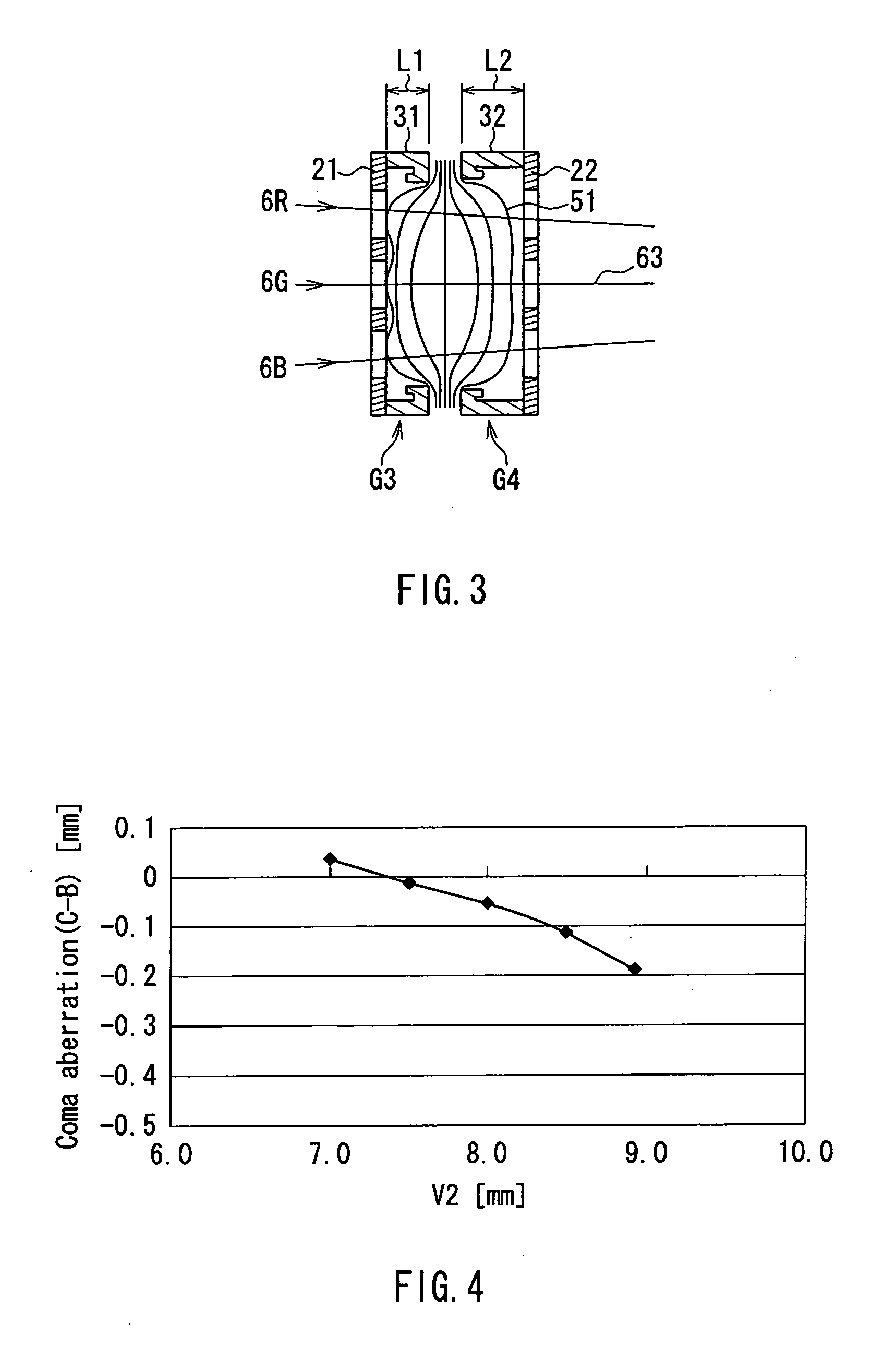
[0068] According to the present invention, even when the aperture of a main lens is enlarged using an electric field superimposing type lens, the coma aberration of a side beam can be suppressed without shortening the horizontal dimension of three electron beam passage apertures formed in an electric field correcting electrode, and a side beam is allowed to arrive at a screen at a position where convergence can be corrected. Thus, the dimension of a beam spot on a screen can be shortened without degrading convergence characteristics.

[0069] Hereinafter, the present invention will be described in detail by way of one example.

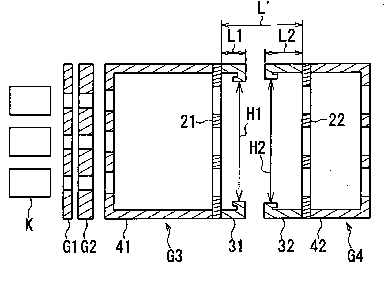
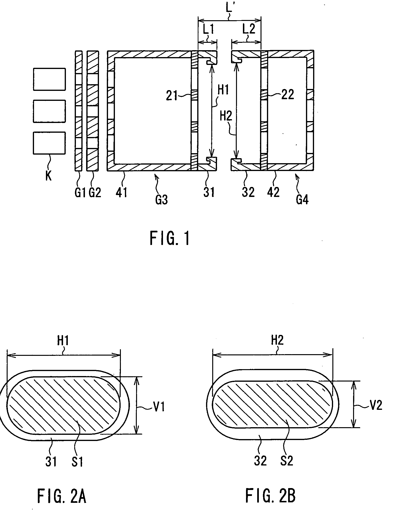
[0070]FIG. 1 shows an in-line type electron gun according to one embodiment of the present invention, which emits three electron beams composed of a center beam and a pair of side beams on both outer sides thereof, aligned on the same horizontal plane. The electron gun includes three cathodes K arranged in a line in a horizontal direction, three heaters (not sho...


PUM


Abstract

A focusing electrode includes an electric field correcting electrode, and a peripheral electrode in which one electron beam passage aperture is formed on a surface opposed to a final-stage accelerating electrode. The final-stage accelerating electrode includes an electric field correcting electrode, and a peripheral electrode in which one electron beam passage aperture is formed on a surface opposed to the focusing electrode. In the focusing electrode, assuming that a distance from an end on the final-stage accelerating electrode side of the peripheral electrode to the electric field correcting electrode is L1, horizontal and vertical dimensions of the electron beam passage aperture of the peripheral electrode are H1, V1, and in the final-stage accelerating electrode, assuming that a distance from an end on the focusing electrode side of the peripheral electrode to the electric field correcting electrode is L2, and horizontal and vertical dimensions of the electron beam passage aperture of the peripheral electrode are H2, V2, relationships: L1<L2 and V1 / H1>V2 / H2 are satisfied. Because of this, the occurrence of a coma aberration of a side electron beam and the degradation in convergence are suppressed, and the dimension of a beam spot on a phosphor screen can be decreased.

Description

BACKGROUND OF THE INVENTION [0001] 1. Field of the Invention [0002] The present invention relates to a color cathode ray tube and an electron gun used therein. In particular, the present invention relates to an in-line type electron gun that enhances the resolution on a phosphor screen, and a color cathode ray tube with the in-line type electron gun mounted therein. [0003] 2. Description of Related Art [0004] In general, as shown in FIG. 10, a color cathode ray tube includes an envelope composed of a panel 1 and a funnel 2 that is integrally connected to the panel 1. On an inner surface of the panel 1, a phosphor screen 3 composed of stripe-shaped or dot-shaped phosphor layers of three colors emitting blue, green, and red light is formed, and a shadow mask 4 with a number of electron beam passage apertures formed thereon is provided so as to be opposed to the phosphor screen 3. An electron gun 7 emitting three electron beams 6B, 6G, 6R is provided in a neck 5 of the funnel 2. [0005]...

Claims


Application Information

Patent Timeline
Patent Type & Authority Applications(United States)
IPC IPC(8): H01J29/50
CPCH01J29/488
Inventor SATO, KAZUNORI
Owner MATSUSHITA TOSHIBA PICTURE DISPLAY CO LTD
Learn More