Organic light emitting diode backlight inside LCD

Inactive Publication Date: 2006-05-25
ORGANIC LIGHTING TECH
View PDF4 Cites 53 Cited by
  • Summary
  • Abstract
  • Description
  • Claims
  • Application Information

AI Technical Summary

Benefits of technology

[0015] It is an object of this invention to provide an internal backlight to LCD for better light coupling efficiency and thus maximize the optical efficiency of LCD.
[0016] It is another object of this invention to integrate OLED backlight inside LCD making use of only two substrates and thus obtain a single compact unit that contains bot

Problems solved by technology

Further, in manufacturing, the assembly cost is high to assemble all the optical components with light sources like Light Emitting Diodes (LEDs) and fluorescent lamps (FLs).
One major drawback of this invention is that the device can not work because OLED is sensitive to moisture and other chemicals inside LCD and nee

Method used


Image

  • Organic light emitting diode backlight inside LCD
  • Organic light emitting diode backlight inside LCD
  • Organic light emitting diode backlight inside LCD

Examples


Embodiment Construction

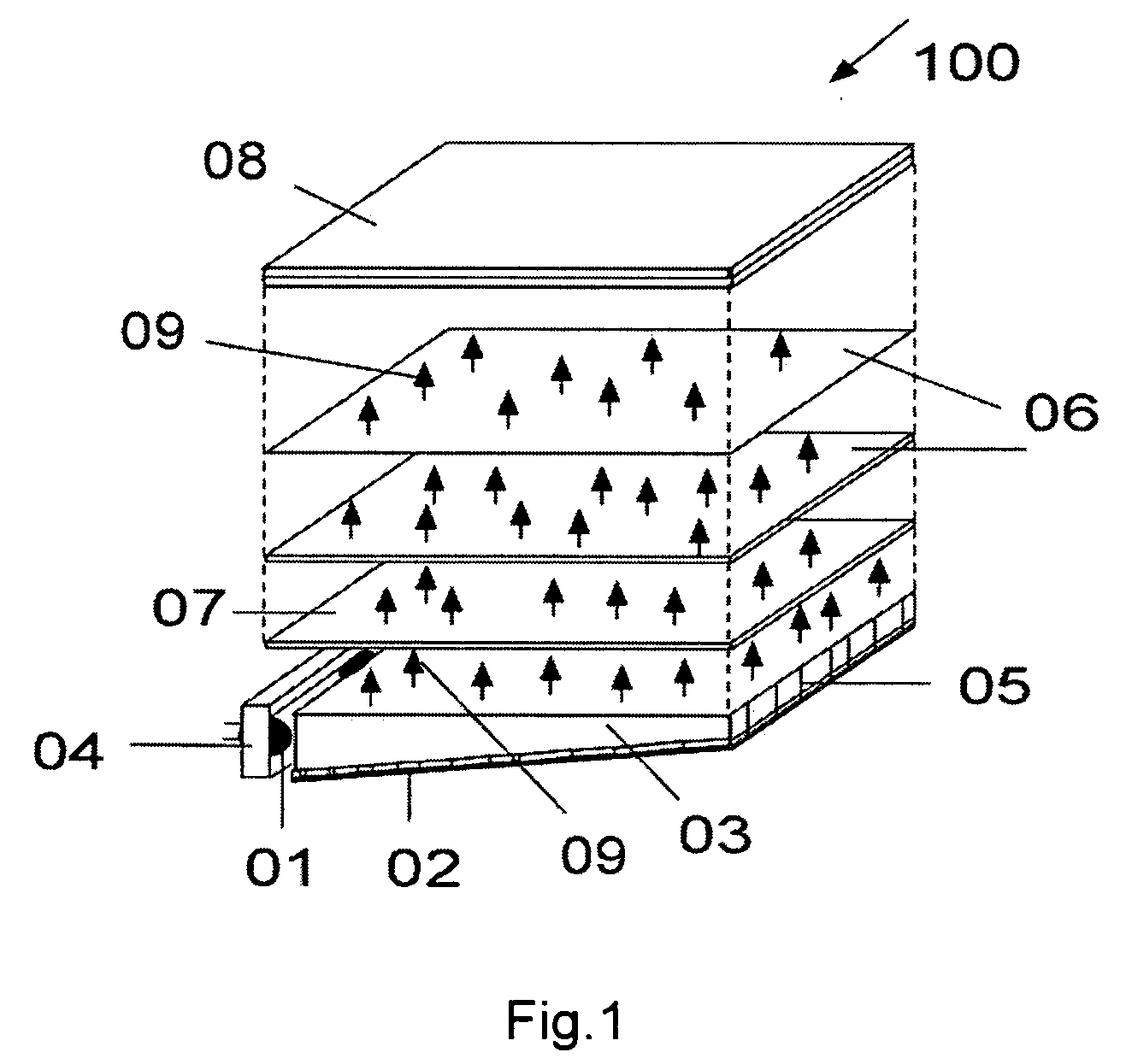
[0023]FIG. 1 shows the isometric view 100 of the traditional backlight for LCD employing optical components according to a prior art. The light source 01 is either Light Emitting Diode (LED) or Cold Cathode Fluorescent Lamp (CCFL). A reflector 04 is placed behind the light source 01 to reflect the light forward to a light guide 03 which has a patterned reflector 02 to send uniform sheet of reflected light 09 towards the back surface of LCD 08. A reflector 05 at far end of light guide 03 prevents light loss in the lateral direction. A diffuser sheet 07 above the wedge light guide makes the light uniform and the two prism sheets 06 over the diffuser sheet 07 collimates the light in to the useful viewing angle of LCD 08.

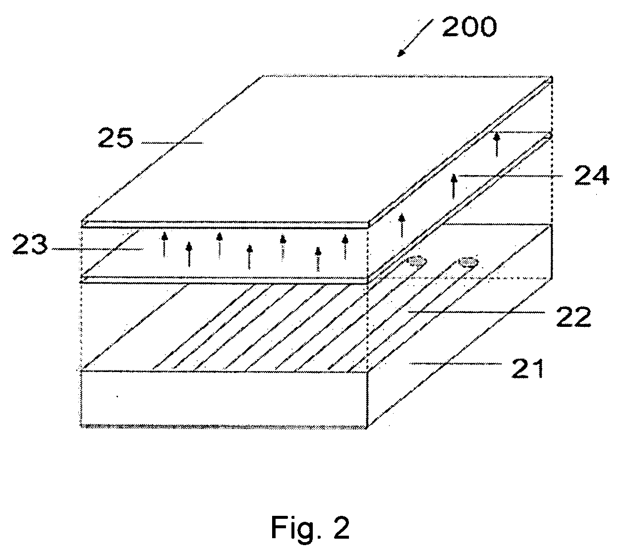
[0024]FIG. 2 shows the isometric view 200 of a direct backlight according to another prior art. The backlight box 21 contains linear fluorescent lamps 22 and a diffuser 23 assembled over the fluorescent lamps 22. The diffused light 24 uniformly backlights the LCD 25. F...


PUM


Abstract

A planar organic light emitting diode (OLED) light source is processed on one of the substrates of a liquid crystal display (LCD) and sealed pin-hole free such that LCD processes, including internal polarizer, can be carried out on OLED without affecting the integrity of OLED and LCD. Both devices are held in alignment and hermetaically sealed between two substrates thus forming an integrated device and on application of suitable voltages to these devices OLED generates light and efficiently couples the light to LCD to function efficiently as a full color display.

Description

CROSS REFERENCE TO RELATED APPLICATION [0001] Benefit of Provisional patent Application No. 60 / 631,040 filed Nov. 24, 2004 [0002] U.S. patent application # 20040170861—Culligan Sean et.al—“Organic Light Emitting Diode for production of polarized light”[0003] U.S. patent application # 20050007517 A1—Munisamy Anandan—“Organic Light Emitting Diode Backlight Integrated LCD”[0004] U.S. patent application Publication # US2003 / 0063231 A1—Yuan-Tung Dai et.al—“LCD panel integrated with OLED”.OTHER PUBLICATIONS [0005] SID'04 Digest—Book I, p. 695 Si Nitride passivation layer, Ar plasma assisted<120 C 30 A / sec, “A thin film encapsulation stack for PLED and OLED displays” F. J. H. Van Assche et.al [0006] SID'04 Digest—p. 1170-1173“Current Status and future prospect of in-cell polarizer technology”—Y. Ukai et.al [0007] SID'04 Digest—p. 1384-1387—“Thin film encapsulation-silicon nitride-silicon oxide-silicon nitride-silicon oxide-silicon nitride (NONON)”—H. Lifka et.al—plasma enhanced CVD. [00...

Claims


Application Information

Patent Timeline
IPC IPC(8): G02F1/1335
CPCG02F1/133603G02F2001/133565H01L27/3232H01L2251/5315G02F1/133565H10K59/50H10K2102/3026
Inventor ANANDAN, MUNISAMY
Owner ORGANIC LIGHTING TECH
Why Eureka
Try Eureka