
Reticle-carrying container

a technology for reticles and containers, applied in the field of reticles, can solve problems such as the inability to form accurate circuit patterns, and achieve the effects of enhancing the shock absorption function, and supporting the reticle more elastically

Inactive Publication Date: 2006-05-25
MIRAIAL CO LTD
View PDF8 Cites 13 Cited by
  • Summary
  • Abstract
  • Description
  • Claims
  • Application Information

AI Technical Summary

Benefits of technology

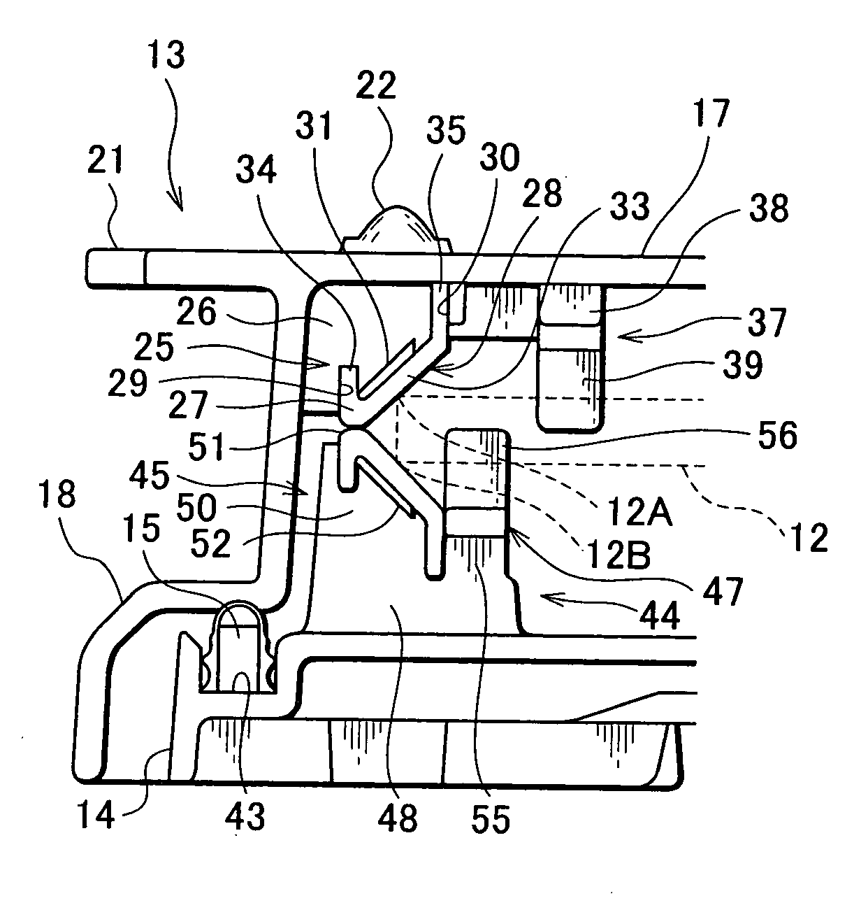
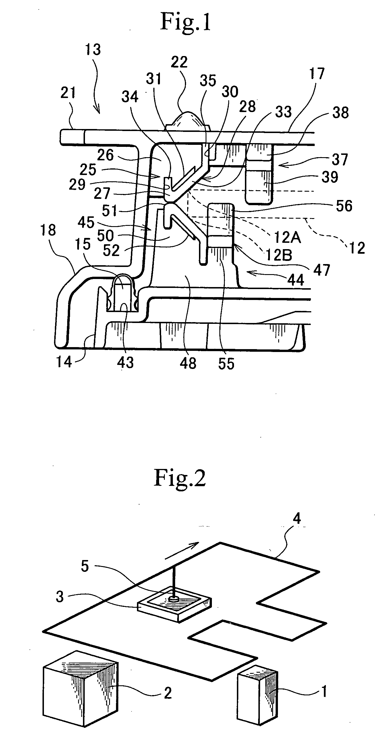
[0019] This structure allows each of the retainers to contact the upper corner or lower corner of peripheral edge of the reticle, thereby supporting the reticle elastically. Moreover, each of the retainers supports the reticle by the inclined plane so that the reticle can be supported without being shifted.
[0020] In addition to the inclined plane, each of the retainers may include a concave portion formed on the inside of the inclined plane. The concave portion enables a shock-absorbing function of allowing the deformation of the inclined plane and supporting the reticle elastically, at the time of contact with the upper corner or the lower corner of peripheral edge of the reticle.
[0021] With this structure, each of the retainers molded of an elastic member supports the reticle elastically through contact with the upper corner or the lower corner of peripheral edge of the reticle, and the concave portion of the retainer forms a gap that allows the deformation of the inclined plane. This makes it possible to enhance the shock-absorbing function and support the reticle more elastically.
[0022] Each of the retainers supports the reticle elastically and also the inclined plane retains the reticle without a shift. This allows the reticle to be held elastically and reliably.
[0023] Moreover, the concave portion allows the deformation of the inclined plane and enhances the shock-absorbing function, making it possible to support the reticle in a more elastic and secure manner.
[0024] Furthermore, the supporting portions holds the reticle without making contact with the mask pattern formed on the reticle surface, thereby preventing damage and abrasion of the pattern on the reticle.

Problems solved by technology

If the reticles are contaminated with dust, etc. or damaged by contact with other components, it is impossible to form an accurate circuit pattern.
This causes the vibrations of the reticle-carrying container to be conveyed directly to the reticle, which is undesirable in treating a precision component.

Method used


Image

  • Reticle-carrying container
  • Reticle-carrying container
  • Reticle-carrying container

Examples


Embodiment Construction

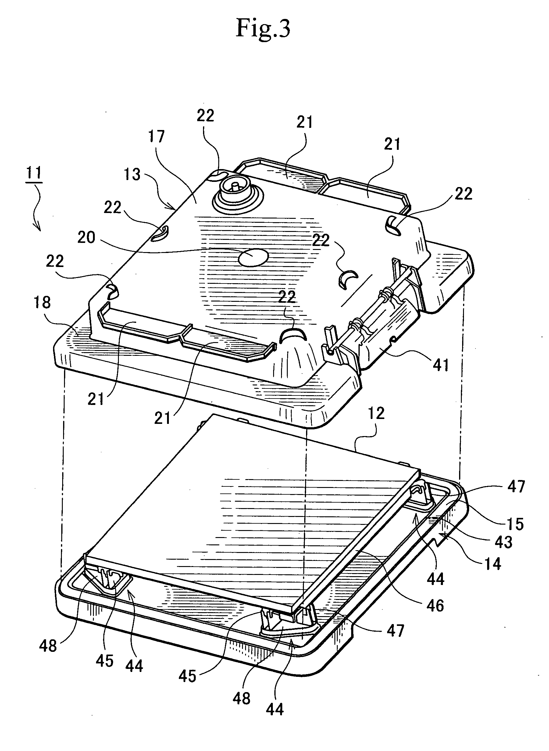
[0032] The embodiment of the present invention is described below with reference of the accompanied drawings. The apparatus used in the photolithography process or the like is the same as the conventional one described in relation to the above stated related arts. Thus, a description is here provided only as to the reticle-carrying container. FIG. 1 is a cross sectional view showing the major components of the reticle-carrying container according to this embodiment, FIG. 3 is a perspective view showing the reticle-carrying container according to this embodiment in which the pod and the door are separated from each other, FIG. 4 is a side cross sectional view showing the reticle-carrying container according to this embodiment, FIG. 5 is a perspective view of the door as seen from its bottom, FIG. 6 is a cross sectional view of major components of the membrane filter, and FIG. 7 is a cross sectional view of major components of the wireless tag.

[0033] As shown in FIG. 3 and FIG. 4, a ...


PUM

PropertyMeasurementUnit
photosensitiveaaaaaaaaaa
densityaaaaaaaaaa
outer circumferenceaaaaaaaaaa

Abstract

The present invention supports a reticle 12 in a safe and secure manner. A reticle-carrying container 11 includes a pod 13 for storing the reticle 12, a door 14 and a seal 15 for blocking and sealing hermetically the pod 13. A pair of retile retainers 25 and 45 is provided on the insides of the pod 13 and door 14. Each of the reticle retainers 25 and 45 includes an inclined plane 28 that contacts an upper corner 12A or a lower corner 12B of peripheral edge of the reticle 12 and supports the reticle 12 elastically. The inside of the inclined plane 28 is provided with concave portions 31 and 52 that enables a shock-absorbing function of allowing the deformation of the inclined plane 28 and supporting the reticle elastically, at the time of contact with the upper corner 12A or the lower corner 12B of peripheral edge of the reticle 12.

Description

CROSS-REFERENCE TO RELATED APPLICATION [0001] This application claims, under 35 USC 119, priority of Japanese application No. 2004-339375 filed Nov. 24, 2004. BACKGROUND OF THE INVENTION [0002] 1. Field of the Invention [0003] The present invention relates to a reticle-carrying container for carrying a reticle used for a light exposure apparatus or the like that transfers a set pattern to a substrate. [0004] 2. Description of the Background Art [0005] Semiconductor devices and liquid crystal display devices are manufactured in process of photolithography. In this process, an image of pattern formed on a reticle (including a photo mask) is projected and transferred by a light exposure apparatus onto a substrate such as a semiconductor wafer and a glass plate. At that time, the transferred pattern reacts with a photosensitive agent applied to the substrate, and then a circuit is formed through the subsequent operations. [0006] During this process, a reticle is stored in a dedicated re...

Claims


Application Information

Patent Timeline
Patent Type & Authority Applications(United States)
IPC IPC(8): G03B27/62B65D25/10B65D25/20B65D85/86G03F1/66G03F7/20H01L21/027H01L21/673
CPCG03F1/66G03F7/70741H01L21/67005H01L21/67353H01L21/67359H01L21/67383H01L21/67386
Inventor MATSUTORI, CHIAKIYANAGIHARA, KOICHI
Owner MIRAIAL CO LTD
Learn More