Log-sampled filter system

a filter system and filter technology, applied in the field of digital filters, can solve the problems of high complexity of fir filters, excessive time or frequency resolution, and excessive sampling of low frequency components

Active Publication Date: 2006-05-25
HARMAN INT IND INC
View PDF8 Cites 23 Cited by
  • Summary
  • Abstract
  • Description
  • Claims
  • Application Information

AI Technical Summary

Benefits of technology

[0011] The filter processes non-linearly sampled signals with a structure that allows the filter frequency response to be specified in fewer samples. The frequency response of the filter system may be adjusted in real-time using a gain section of the system. The gain section may include a gain element associated with the real portion of the frequency spectrum and a gain element associated with the imaginary portion of the frequency spectrum. The gain elements may be calculated by dividing each point specified in the frequency response into the real and imaginary parts. This allows the gain elements to directly specify the frequency response of the filter system.

Problems solved by technology

These filters often provide an excessive amount of time or frequency resolution.
Wile this high sample rate may be necessary for the high frequency components of the signal, linear sampling across all frequencies results in excessive sampling for the low frequency components.
Furthermore, the high sample rate would typically result in a FIR filter with high complexity due to numerous filter coefficients needed to specify the impulse response.
Moreover, the high complexity of FIR filters often creates obstacles to implementation.
For example, selection of the suitable filter coefficients to elicit a desired frequency response can be challenging.
If the desired frequency response changes, the filter designer must go through the challenging process of selecting different filter coefficients, likely employing optimization software.
These optimization techniques render real-time adjustments to the filter coefficients to meet changing desired frequency responses extremely difficult and costly in terms of processing resources.

Method used


Image

  • Log-sampled filter system
  • Log-sampled filter system
  • Log-sampled filter system

Examples


Embodiment Construction

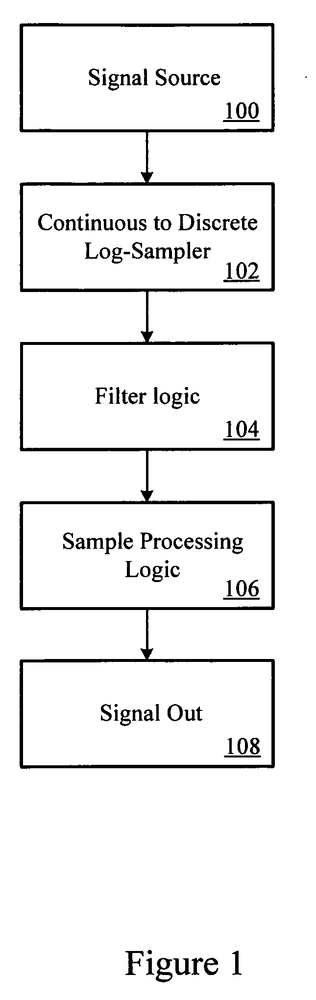
[0028]FIG. 1 shows an example signal processing system with filter logic. The system receives an input signal from a signal source 100. In many cases, the signal source 100 may provide a continuous signal, such as an electrical signal from a transducer. For example, where the signal source 100 provides a continuous signal, the system may sample the input signal with a continuous to discrete sampler 102. The sampler 102 converts the continuous signal into a discrete-time signal (i.e., digital signal).

[0029] The system may include a filter logic 104 configured to filter the discrete-time signal. For example, the filter logic 104 may be configured as a low pass, high pass, bandpass or other filter. The filter logic 104 may be implemented in hardware and / or software. However, the filter logic 104 may be implemented with less hardware and software resources than traditional filters. The filter logic 104 may include discrete logic or circuitry, a mix of discrete logic and a processor whi...


PUM


Abstract

This invention provides a filter system which may be implemented with less hardware and software resources than traditional filters. In addition, the filter system structure reduces the complexities typically associated with filter design by permitting direct specification of the filter frequency response. Thus, the filter system may adaptively change the filter frequency response on the fly without incurring excessive time or computational costs. The filter system may provide a filtered signal output to any subsequent processing system, such as a voice recognition system or audio reproduction system.

Description

PRIORITY CLAIM [0001] This application claims the benefit of U.S. Provisional Application No. 60 / 623,388, filed Oct. 29, 2004, which is incorporated herein by reference.BACKGROUND OF THE INVENTION [0002] 1. Technical Field [0003] This invention relates to digital filters and particularly to finite impulse response filters. [0004] 2. Related Art [0005] Digital signal processing (“DSP”) is used in a wide variety of devices, such as televisions, audio devices, hearing aids, computers and cellular phones. These devices employ DSP techniques to process signals in a variety of ways. For example, digital filtering techniques may be used to improve signal quality or to extract important information. In other cases, digital filters may be used to restore a signal that has been distorted in some way. [0006] A digital filter, such as a finite impulse response (“FIR”) filter, typically includes a number of equally spaced taps. Each tap is separated by a delay line and is multiplied by a filter ...

Claims


Application Information

Patent Timeline
Patent Type & Authority Applications(United States)
IPC IPC(8): H04B1/10
CPCH03H17/0261H03H17/028H03H17/06H03H17/0621H03H2218/04
Inventor KEELE, D. BROADUS JR.
Owner HARMAN INT IND INC
Why Eureka
Try Eureka