Permanent magnet type rotating electrical machine

a permanent magnet and rotating electrical machine technology, applied in the direction of magnetic circuit rotating parts, magnetic circuit shape/form/construction, battery/fuel cell control arrangement, etc., can solve the problems of large torque required per unit bulk and imposing thermal limitations on current density, and achieve the effect of effective utilization

Active Publication Date: 2006-06-01
HITACHI ASTEMO LTD
View PDF13 Cites 60 Cited by
  • Summary
  • Abstract
  • Description
  • Claims
  • Application Information

AI Technical Summary

Benefits of technology

[0020] According to the present invention having the above-mentioned features, when the nonmagnetic portions are formed on both sides of the permanent magnet in the circumferential direction, a peak value of induced voltage can be suppressed and therefore a permanent magnet type rotating electrical machine suitable for driving a vehicle can be obtained.
[0021] Also, according to the present invention, a basic wave component of induced voltage can be increas

Problems solved by technology

In the permanent magnet type rotating electrical machine used for vehicle driving, torque required per unit bulk is very large.
However

Method used


Image

  • Permanent magnet type rotating electrical machine
  • Permanent magnet type rotating electrical machine
  • Permanent magnet type rotating electrical machine

Examples


Embodiment Construction

[0062] Embodiments of the present invention will be described below with reference to the drawings.

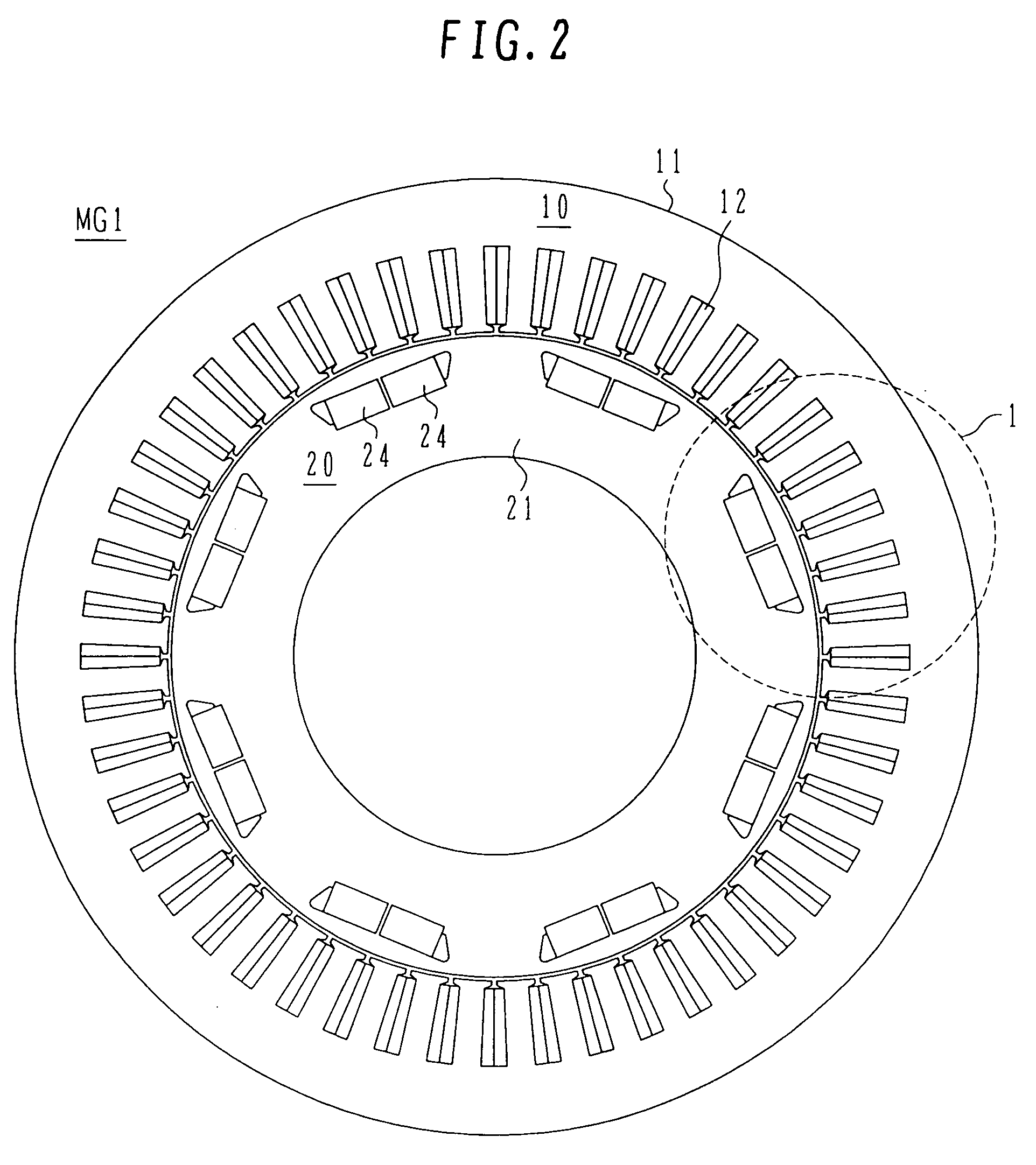
[0063] With reference to FIG. 4, a description is first made of the construction of a vehicle to which a motor generator (permanent magnet type rotating electrical machine) according to one embodiment of the present invention is applied. This embodiment is described, by way of example, in connection with a hybrid electric vehicle (HEV) having two different motive power sources.

[0064] The hybrid electric vehicle of this embodiment is a four-wheel drive vehicle in which front wheels FLW, FRW are driven by an engine (internal combustion engine) ENG and a motor generator MG1, and rear wheels RLW, RRW are driven by a motor generator MG2. While this embodiment is described as driving the front wheels FLW, FRW by the engine ENG and the motor generator MG1 and driving the rear wheels RLW, RRW by the motor generator MG2, the front wheels FLW, FRW may be driven by the motor generator MG1, and ...


PUM


Abstract

A permanent magnet type rotating electrical machine that is capable of producing a higher output and is suitable for high-speed rotation. A pair of nonmagnetic portions are formed in a rotor core at opposite ends of each pole. The waveform of induced voltage and a motor voltage are adjusted based on two parameters, i.e., an angle covering minimum magnetic path portions formed by the nonmagnetic portions and a magnet width. Assuming that a circumferential pitch of teeth cores with respect to a rotor axis is τs (degree) and an opening angle contained by a circumferential width between radial width minimum points of the pair of magnetic path portions with respect to the rotor axis is θ (degree), θ≈(n+Y)×τs (n: integer larger than 0) is met. Y=0.5 is set when the stator windings are wound in a distributed winding way, and Y=0.9-1.2 is set when they are wound in a concentrated winding way. The magnet forming one pole is divided into two parts, and a bridge portion is formed between the two divided magnet parts.

Description

BACKGROUND OF THE INVENTION [0001] 1. Field of the Invention [0002] The present invention relates to a permanent magnet type rotating electrical machine. [0003] 2. Description of the Related Art [0004] A permanent magnet type rotating electrical machine, in particular, a permanent magnet type rotating electrical machine used for vehicle driving, is required to have a smaller size and a higher output, including an inverter that serves as a control circuit for the rotating electrical machine. Especially, there is a demand for a permanent magnet type rotating electrical machine that is capable of outputting large torque in a low-speed rotation range and maintaining a high output in a high-speed rotation range as well. To meet such a demand, many of permanent magnet type rotating electrical machines have hitherto been practiced as the embedded permanent magnet type provided with auxiliary salient poles, which can not only perform field weakening control, but also utilize reluctance torq...

Claims


Application Information

Patent Timeline
IPC IPC(8): H02K21/12H02K1/27
CPCH02K1/276Y02T10/641B60L11/123B60L11/1861B60L11/1868B60L15/007B60L15/2009B60L2210/40B60L2240/12B60L2240/421B60L2240/423B60L2240/441B60L2240/443Y02T10/7077Y02T10/7044Y02T10/7005Y02T10/7241Y02T10/7066Y02T10/7275Y02T10/6217Y02T10/642B60L7/14B60L50/61B60L58/12B60L58/20Y02T10/62Y02T10/64Y02T10/70Y02T10/72Y02T10/7072
Inventor HINO, NORIAKIMATSUNOBU, YUTAKATAJIMA, FUMIOYASUHARA, TAKASHI
Owner HITACHI ASTEMO LTD
Why Eureka
Try Eureka