Method and apparatus for controlling output current of a cascaded DC/DC converter

a technology of dc/dc converter and output current, applied in the direction of electric variable regulation, process and machine control, instruments, etc., can solve problems such as transient performance problems and start-up of topologies

Active Publication Date: 2006-06-01
MICROCHIP TECH INC
View PDF5 Cites 106 Cited by
  • Summary
  • Abstract
  • Description
  • Claims
  • Application Information

AI Technical Summary

Problems solved by technology

However, conventional control methods when applied to cascaded converter topologies suffer st

Method used


Image

  • Method and apparatus for controlling output current of a cascaded DC/DC converter
  • Method and apparatus for controlling output current of a cascaded DC/DC converter
  • Method and apparatus for controlling output current of a cascaded DC/DC converter

Examples


Embodiment Construction

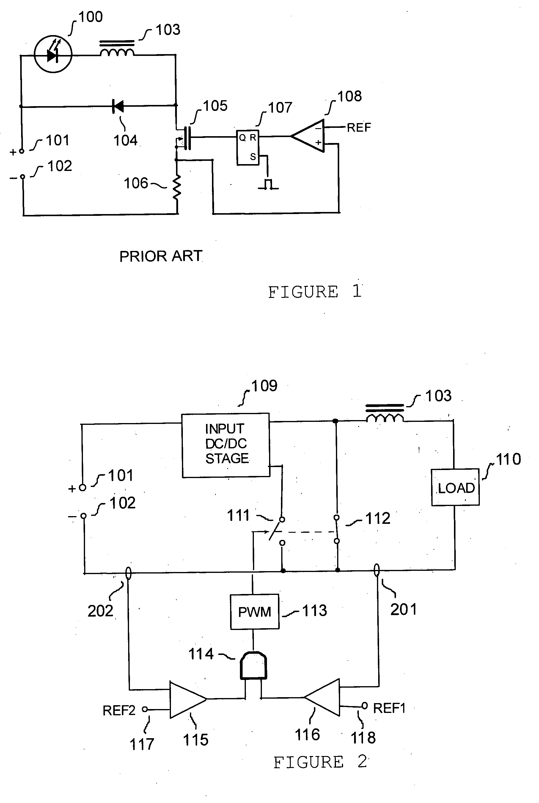
[0019] A buck converter is a basic single-inductor DC / DC converter topology characterized by a step-down voltage transfer ratio. The buck converter is useful for driving light emitting diodes due to its continuous output current. Controlling a buck LED driver can be reduced to merely open-loop control of peak current in the inductor. Easy implementation of PWM dimming is another attractive feature of an open-loop controlled buck converter. Simply switching its control circuit on and off at a few hundred Hertz provides PWM dimming of the LED lamp without subjecting it to any current overshoots, and achieves a wide dynamic range of PWM dimming.

[0020] However, buck converters have several disadvantages. The disadvantages of the buck converter include: step-down only DC transfer ratio, high input current ripple, poor control over output current when operating with a large step-down ratio, poor input power factor when utilized as an AC / DC converter for offline LED driving.
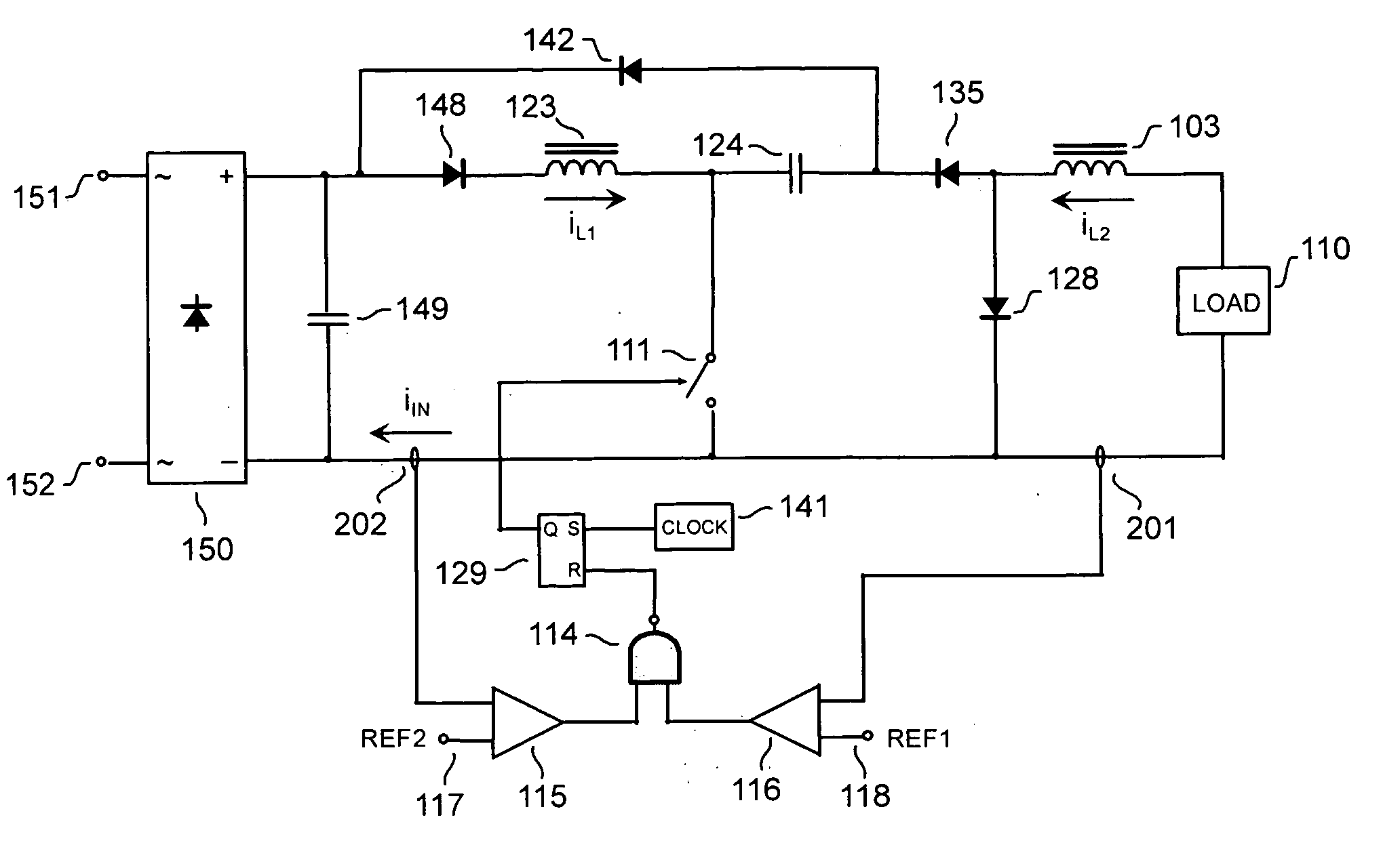
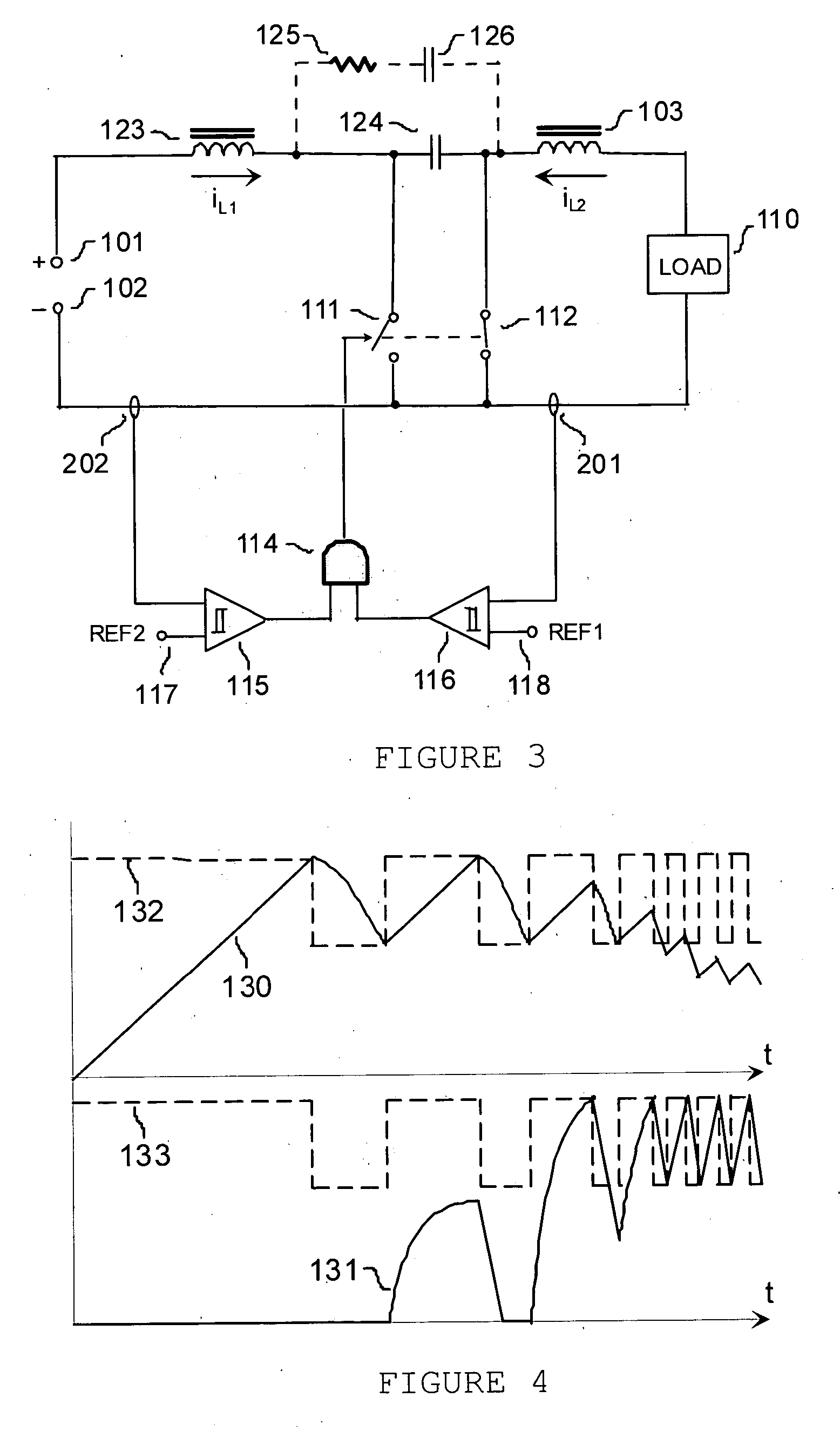
[0021] Cascad...


PUM


Abstract

A circuit and a method for controlling output current of cascaded switching power converters having a buck type output stage are disclosed. The circuit comprises two comparators for sensing input and output current, a logic gate for processing the output states of the comparators, and a pulse width modulator circuit for receiving the output of the logic gate and for controlling a switching power converter in accordance with this output. The method comprises simultaneous monitoring current in the stages of the converter, comparing the currents to the corresponding reference levels, generating the corresponding error signals, and controlling a pulse-width modulator circuit of a switching converter in accordance with these error signals.

Description

RELATED APPLICATION [0001] This application is related to U.S. Provisional Application Ser. No. 60 / 631,514, filed Nov. 29, 2004, in the name of the same inventors listed above, and entitled, “METHOD AND APPARATUS FOR CONTROLLING OUTPUT CURRENT OF A CASCADED DC / DC CONVERTER” The present patent application claims the benefit under 35 U.S.C. §119(e).FIELD OF THE INVENTION [0002] The present invention relates generally to power supplies, and more specifically to a method and apparatus for controlling switching power converters powering light emitting diodes (LED) and other current-fed devices. BACKGROUND OF THE INVENTION [0003] Development of high brightness light emitting diodes (HB-LED) in recent years has created a demand for a new class of power sources—LED drivers. The present applications of HB-LEDs include, but are not limited to: traffic signals, decorative lighting, automotive lighting (head and tail lights), etc. The LED driver is expected to supply a constant current with low...

Claims


Application Information

Patent Timeline
IPC IPC(8): G05F1/40G05F1/618
CPCH02M1/4208H02M3/155H02M2001/4291Y02B70/126H02M1/4291Y02B70/10
Inventor MEDNIK, ALEXANDERTIRUMALA, ROHIT
Owner MICROCHIP TECH INC
Why Eureka
Try Eureka