Interferometric optical analyzer and method for measuring the linear response of an optical component

an optical analyzer and linear response technology, applied in the field of optical components, can solve the problems of time-consuming and expensive approaches, redundant measurements, and high probability, and achieve the effect of reducing or reducing the disadvantages of known instruments

Inactive Publication Date: 2006-06-01
EXFO ELECTRO OPTICAL ENG
View PDF15 Cites 27 Cited by
  • Summary
  • Abstract
  • Description
  • Claims
  • Application Information

AI Technical Summary

Benefits of technology

[0015] The present invention seeks to eliminate, or at least mitigate, t...

Problems solved by technology

Such an approach is time consuming and expensive as the component must be connected and reconnected multiple times as well as moved between test stations.
It is also highly likely that redundant measurements would be taken.
Although such systems may overcome the problems associated with connecting and reconnecting the DUT and moving the DUT between test stations, multiple measurements must still be made, and the problem of time consumption remains.
A limitation of these known instruments is that the two signals associated with the two input orthogonal states of polarization launched simultaneously into the DUT are detected, in essence, as modulations of two distinct carriers of different frequencies and so are distinguished separately in the frequency domain.
Such an increase in bandwid...

Method used


Image

  • Interferometric optical analyzer and method for measuring the linear response of an optical component
  • Interferometric optical analyzer and method for measuring the linear response of an optical component
  • Interferometric optical analyzer and method for measuring the linear response of an optical component

Examples


first embodiment

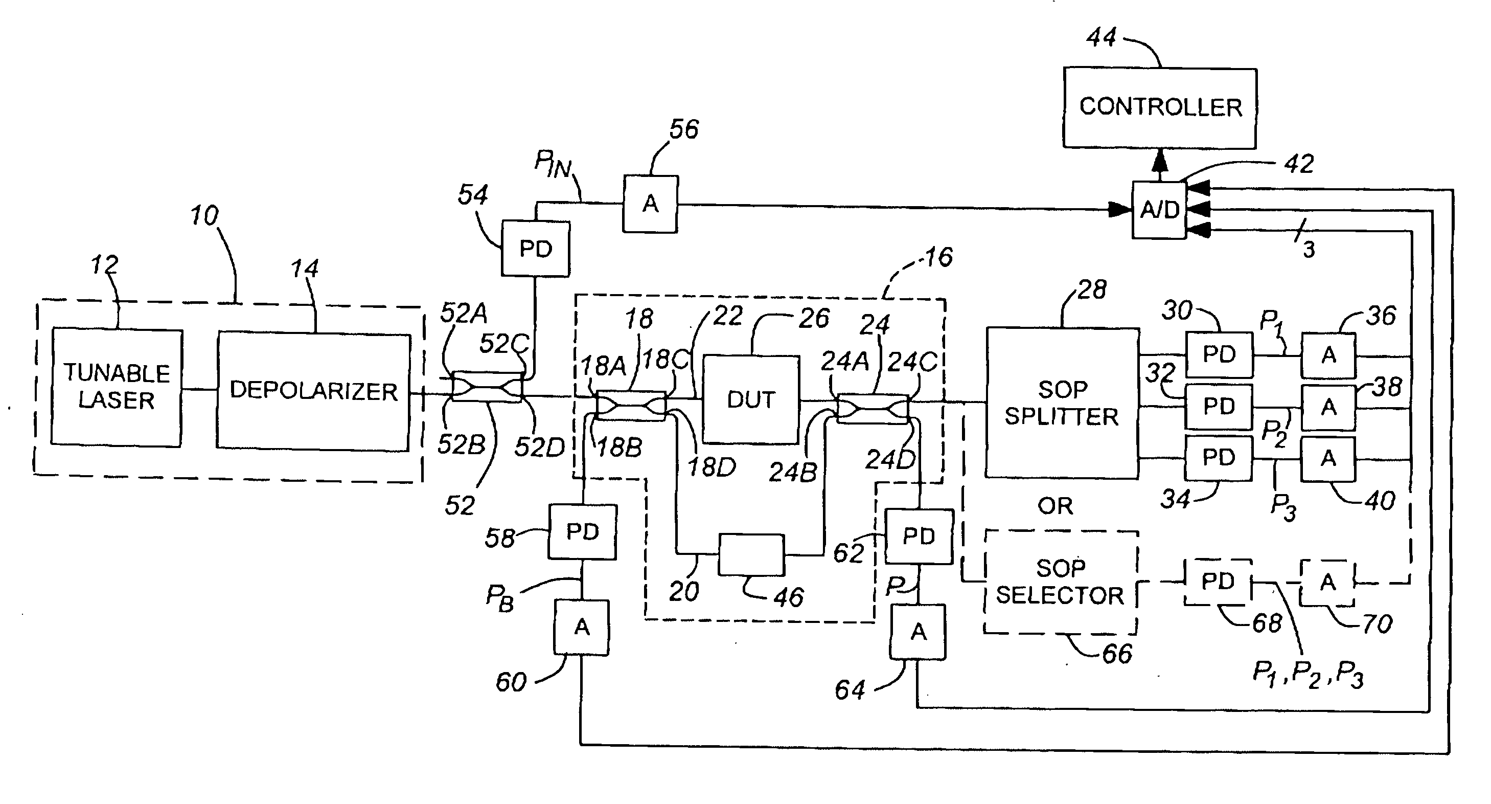
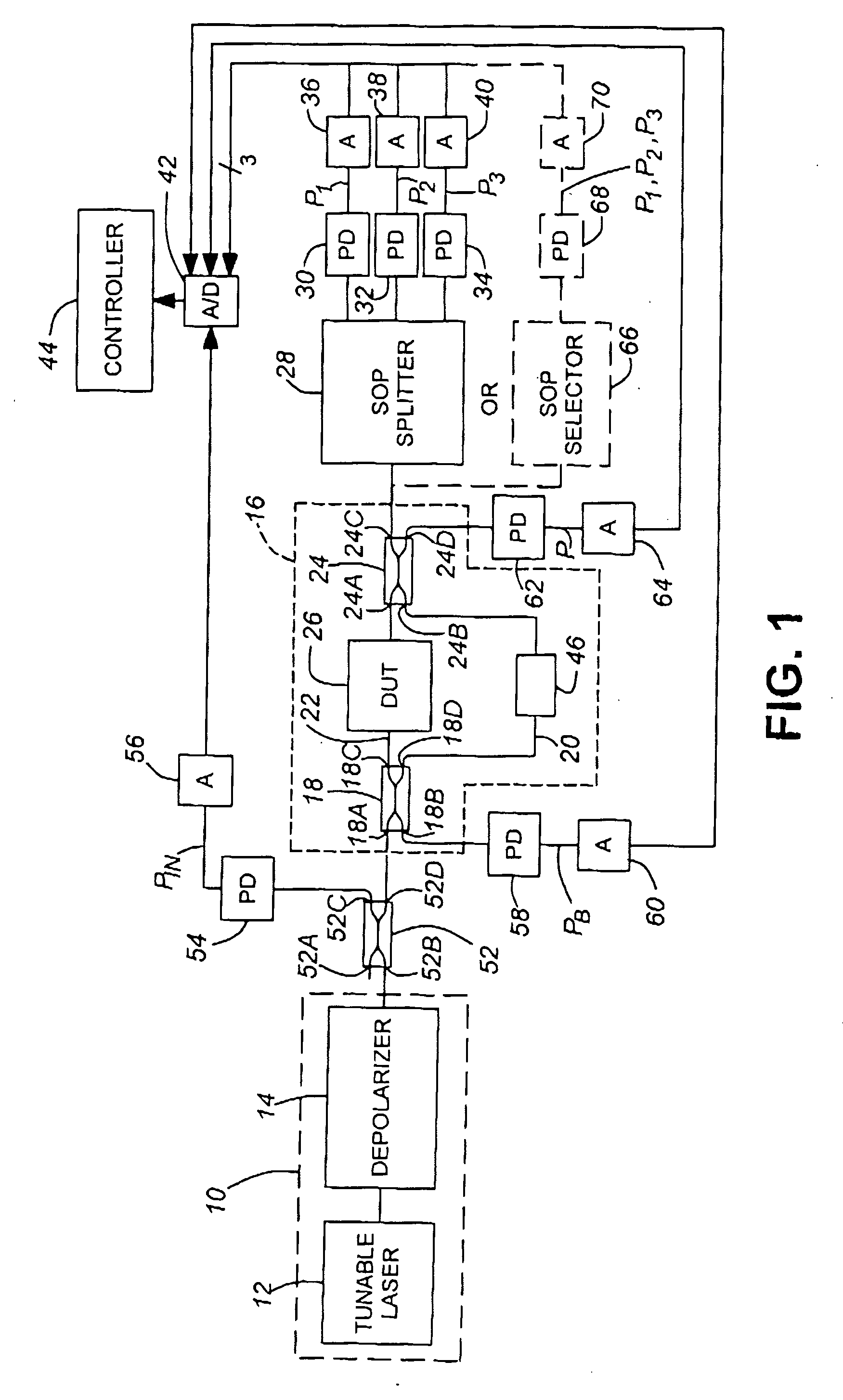
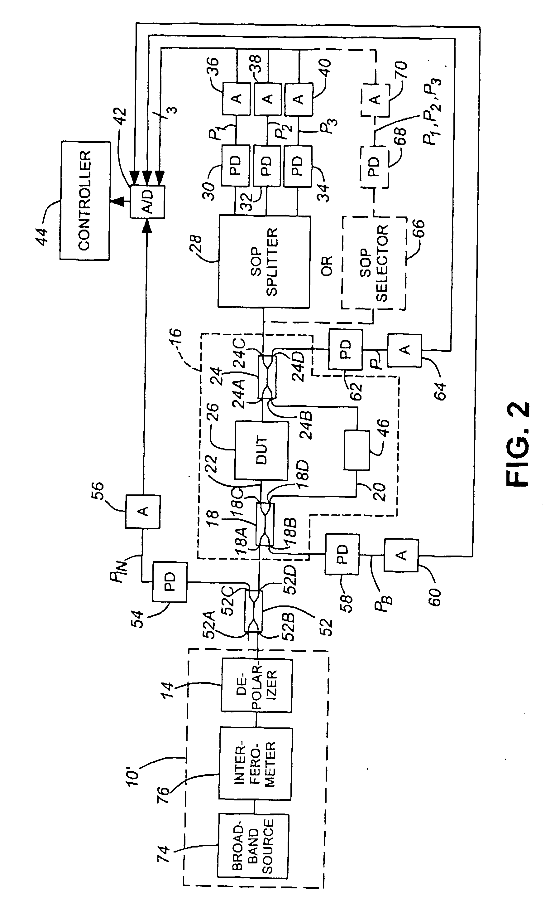
[0057] If the incoherent light source 10′ is an ASE source which emits substantially unpolarized light, the depolarizer 78 may not be needed. However, it maybe included to compensate for any polarization dependency of the LED and / or swept-Michelson interferometer 76, The output of the incoherent light source 10′ is coupled to an input port 52B of the coupler 52, as in the Other components of the embodiment shown in FIG. 2 are similar to those shown in FIG. 1 and so will not be described again.

[0058] It should be appreciated that, in either embodiment, the depolarizer 14 may take any suitable form, providing it scrambles state of polarization rapidly enough.

[0059] The term “depolarized” or “unpolarized”, as used to describe the light leaving the depolarizer 14, is intended to mean that the state-of-polarization (SOP), averaged over a period of time that is sufficiently long, is substantially zero. Hence, while the laser's wavelength is swept and a signal is being detected and sampl...

second embodiment

[0063] It should be appreciated that, although the second embodiment has the swept-Michelson interferometer before the first interferometer 16, it could be placed after the interferometer 16 without loss of functionality, It is common knowledge among those skilled in this art that the Michelson interferometer used for Fourier transform spectroscopy can be put indifferently at input or output.

[0064] It should be noted that the above-described embodiments measure only three substantially linearly independent SOP, and compute the fourth SOP power P4 required to compute the Jones matrix from the three powers P1, P2, P3 and the total power P, this being allowed by the fact that the observed total power P(υ) is equal to the sum of powers observed along any two orthogonal SOPS. Alternatively, however, a fourth analyzer could be provided with its axis oriented so that the corresponding Stokes vector is opposed to that of one of the other analyzers, i.e., the resulting SOP points are antipod...


PUM


Abstract

An interferometric optical analyzer apparatus comprises a light source, an interferometer and a detection system for determining the linear response, and subsequently any optical parameter, of one or more optical elements using substantially unpolarized light. In one embodiment, the light source supplies substantially unpolarized coherent light over a predetermined range of optical frequencies. The optical element is coupled in one arm of the interferometer and the other arm of the interferometer is used as a reference. The unpolarized light is first passed through the interferometer then through a three-way polarization splitter unit to split the light into at least three light beams according to preselected polarization axes corresponding to three linearly independent states of polarization. The three light beams are coupled to individual detectors and a controller computes Jones matrix elements from the resulting electrical signals. The total polarization independent power may also be determined by an additional detector.

Description

CROSS REFERENCE TO RELATED DOCUMENT [0001] This application claims priority from U.S. Provisional patent application Ser. No. 60 / 631,175 filed Nov. 29, 2004, the contents of which are incorporated herein by reference. [0002] The present application is related to Disclosure Document No. 522,396, entitled “Method and Apparatus for Measuring All Linear Parameters of an Optical Component”, filed in the United States Patent and Trademark Office on Nov. 29, 2002, The entire contents of this Disclosure Document are incorporated herein by reference.BACKGROUND OF THE INVENTION [0003] 1. Technical Field [0004] The invention relates to an interferometric method and apparatus for measuring parameters of a device-under-test (DUT), particularly an optical element, for example an optical fiber, a sensor, a filter, a grating, a coupler, a power splitter, an interferometer, a modulator, a switch, integrated optics, and so on. [0005] 2. Background Art [0006] The deployment of new optical technologies...

Claims


Application Information

Patent Timeline
IPC IPC(8): G01B9/02
CPCG01M11/331G01M11/336G01M11/337G01M11/338
Inventor CYR, NORMAND
Owner EXFO ELECTRO OPTICAL ENG
Why Eureka
Try Eureka