Inter-domain TE-LSP with IGP extensions

a technology of inter-domain te-lsp and extension, applied in the field of computer networks, can solve the problems of path computation at the head-end lsr, burdensome management of interconnected computer networks, domain te-lsps, etc., and achieve the effect of avoiding some of the risks and possible errors

Active Publication Date: 2006-06-01
CISCO TECH INC
View PDF18 Cites 47 Cited by
  • Summary
  • Abstract
  • Description
  • Claims
  • Application Information

AI Technical Summary

Benefits of technology

[0025] Advantageously, the novel technique propagates reachability information for a tail-end node of an established TE-LSP that spans multiple domains to a head-end node of the TE-LSP. By informing the head-end node of the reachability information for the tail-end node, the inventive technique provides an alternative to sub-optimal routing techniques, such as cumbersome manual configuration (e.g., static routing or policy routing), that can avoid some of the risks and possible errors created in such sub-optimal routing techniques.

Problems solved by technology

Since management of interconnected computer networks can prove burdensome, smaller groups of computer networks may be maintained as routing domains or autonomous systems.
One difficulty that arises in crossing domain boundaries is that path computation at the head-end LSR requires knowledge of network topology and resources across the entire network between the head-end and the tail-end LSRs.
Yet service providers typically do not share this information with each other across domain borders.
A known limitation of such inter-domain TE-LSPs lies in the inability to automatically steer traffic onto such TE-LSPs when attempting to reach nodes or prefixes contained within the domain of the tail-end node.
This limitation is primarily due to limited network topology information available to the head-end node.
Currently, this lack of reachability information has required the use of static or policy-based routing, which generally requires manual configuration by a system administrator with prior knowledge of the network topology.
Such alternatives can be cumbersome and limited in their applicability, and in some cases (e.g., misconfiguration) can be the cause of network failure.

Method used


Image

  • Inter-domain TE-LSP with IGP extensions
  • Inter-domain TE-LSP with IGP extensions
  • Inter-domain TE-LSP with IGP extensions

Examples


Embodiment Construction

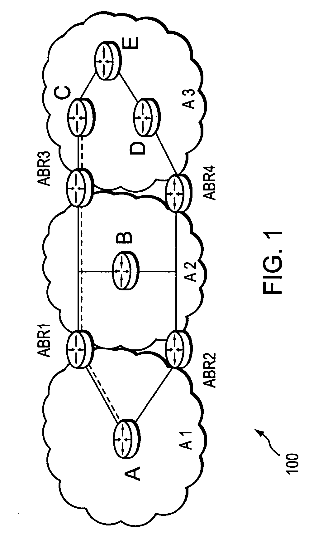
[0036]FIG. 1 is a schematic block diagram of an exemplary computer network 100 comprising areas A1 and A2 having exemplary intradomain routers A and B, respectively, and area A3, which has exemplary intradomain routers C, D, and E. In addition, A1 and A2 share area border routers ABR1 and ABR2, while A2 and A3 share ABR3 and ABR4. As used herein, an area is a collection of routers that share full network topology information with each other but not necessarily with routers outside the area. A collection of areas may be contained within a single autonomous system (AS). The term area as used herein also encompasses the term “level” which has a similar meaning for networks that employ IS-IS as their interior gateway protocol (IGP), in which case the area border routers ABR1-4 are embodied as level 1 / level 2 (L1L2) routers. These examples are merely representative. The terms area and level are used interchangeably herein, as well as the use of ABR, L1L2 routers, and more generally, IGP ...


PUM


Abstract

A technique propagates reachability information for a tail-end node of a traffic engineering (TE) label switched path (LSP) to a head-end node of the TE-LSP in a computer network. The TE-LSP preferably spans multiple domains of the network such that the tail-end node resides in a domain that is different (remote) from the domain of the head-end node. The inter-domain information propagation technique employs an Interior Gateway Protocol (IGP) to transmit the remote reachability information from a target node residing in the same domain as the tail-end node to the head-end node. The head-end node uses the remote information to calculate routes, i.e., address prefixes and associated attributes, reachable from the tail-end node for insertion into its routing table.

Description

RELATED APPLICATION [0001] This application is related to U.S. application Ser. No. ______ (Atty. Docket No. 112025-0600), entitled PROPAGATION OF ROUTING INFORMATION IN RSVP-TE FOR INTER-DOMAIN TE-LSPS, filed by Vasseur et al. on even date herewith, the contents of which is hereby incorporated in its entirety.BACKGROUND OF THE INVENTION [0002] 1. Field of the Invention [0003] The present invention relates to computer networks and more particularly to retrieving reachability information across domains of a computer network. [0004] 2. Background Information [0005] A computer network is a geographically distributed collection of nodes interconnected by communication links and segments for transporting data between end nodes, such as personal computers and workstations. Many types of networks are available, with the types ranging from local area networks (LANs) to wide area networks (WANs). LANs typically connect the nodes over dedicated private communications links located in the same...

Claims


Application Information

Patent Timeline
Patent Type & Authority Applications(United States)
IPC IPC(8): H04L12/56H04L12/28
CPCH04L12/5695H04L45/02H04L45/04H04L45/28H04L45/502H04L47/724H04L47/785H04L47/825H04L47/70
Inventor VASSEUR, JEAN-PHILIPPEPREVIDI, STEFANO B.
Owner CISCO TECH INC
Why Eureka
Try Eureka