Calibration of X-ray reflectometry system

a reflectometry and x-ray technology, applied in the direction of instruments, radiation beam directing means, material analysis using wave/particle radiation, etc., can solve the problems of non-uniform variations in beam intensity, reducing the accuracy of measurement of the xrr spectrum of the sample, and compromising the accuracy of this spectrum, etc., to achieve enhanced precision, the effect of improving the accuracy of the spectrum

Inactive Publication Date: 2006-06-01
BRUKER TECH LTD
View PDF5 Cites 17 Cited by
  • Summary
  • Abstract
  • Description
  • Claims
  • Application Information

AI Technical Summary

Benefits of technology

[0008] Embodiments of the present invention provide devices and methods for calibration of a system for X-ray spectroscopy, such as an XRR system. In these embodiments, an X-ray source irradiates a sample with a beam of X-rays, which is typically focused to a small spot or line on the surface of the sample. A detector array measures the intensity of the X-rays emitted from the surface as a function of angle. In the case of XRR, the X-rays are emitted by specular reflection from the surface, and each detector element in the array receives X-rays at a different angle of reflection. Thus, the system measures an X-ray spectrum of the sample, but the accuracy of this spectrum may be compromised by imperfect alignment of system components and lack of uniformity in the incident X-ray beam. Precise calibration is needed in order to compensate for these flaws. The embodiments described hereinbelow permit the system to be calibrated with enhanced precision and greater speed than methods known in the art.

Problems solved by technology

Thus, the system measures an X-ray spectrum of the sample, but the accuracy of this spectrum may be compromised by imperfect alignment of system components and lack of uniformity in the incident X-ray beam.
Due to non-uniformity in focusing of the X-ray beam onto the surface, however, there are typically non-uniform variations in the beam intensity as a function of angle, which change when the knife edge is inserted into the beam.
The non-uniformity tends to reduce the accuracy of measurement of the XRR spectrum of the sample.

Method used


Image

  • Calibration of X-ray reflectometry system
  • Calibration of X-ray reflectometry system
  • Calibration of X-ray reflectometry system

Examples


Embodiment Construction

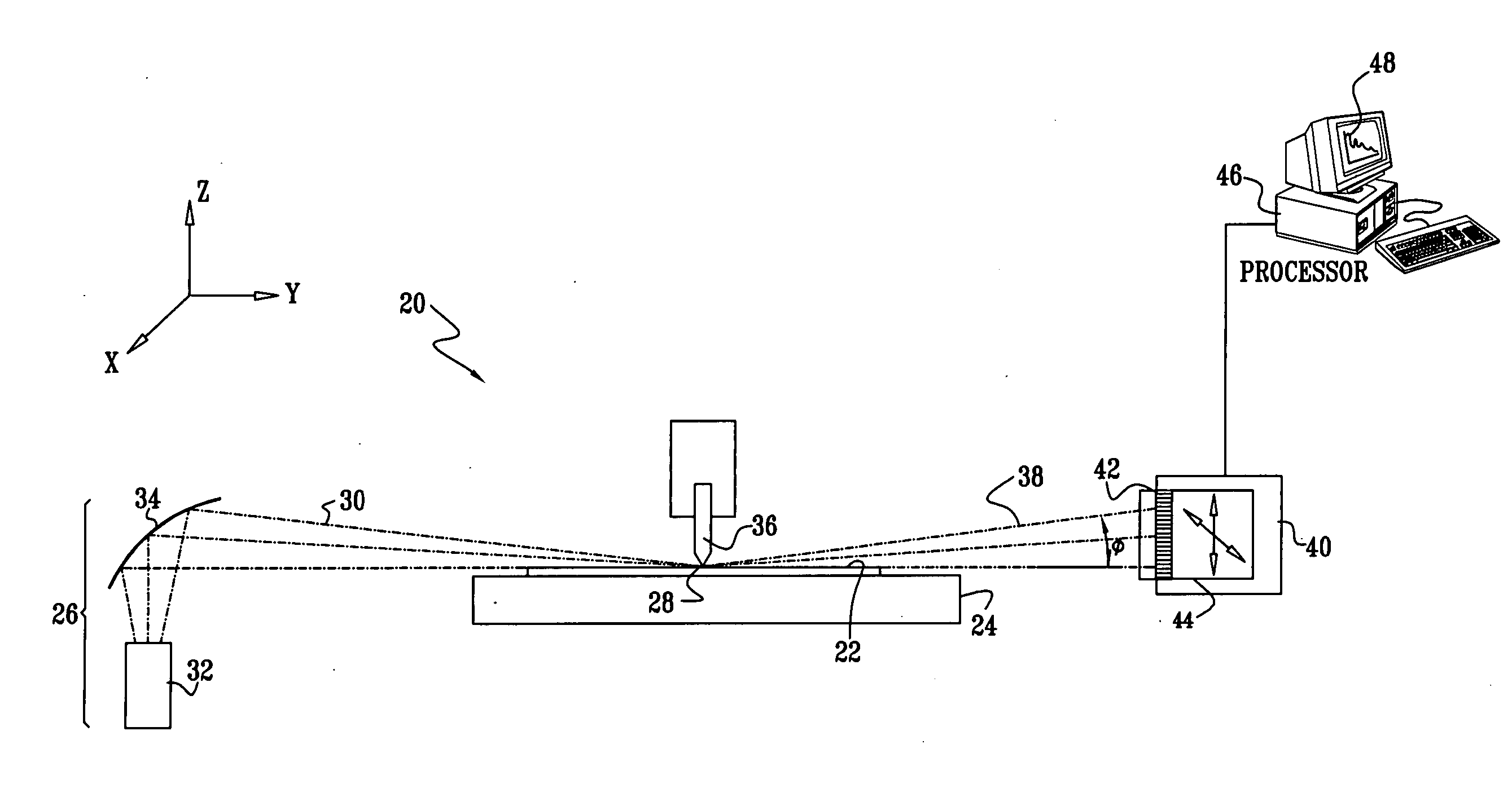
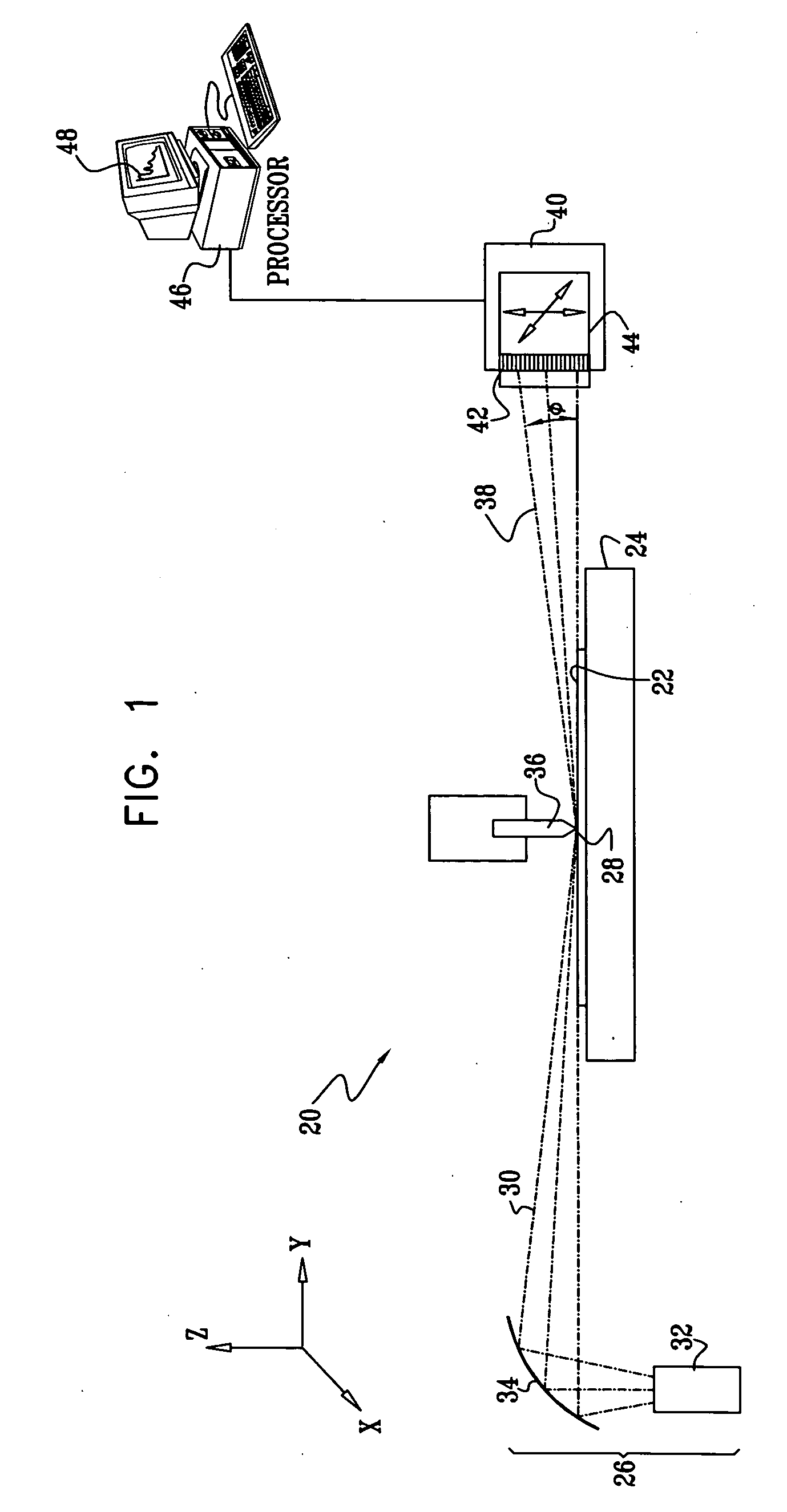
[0120] Reference is now made to FIG. 1, which is a schematic side view of a system 20 for X-ray reflectometry (XRR) of a sample 22, in accordance with an embodiment of the present invention. Sample 22 is mounted on a mounting assembly, such as a motion stage 24, allowing accurate adjustment of the position and orientation of the sample. An X-ray source 26 irradiates a small area 28 on sample 22 with a converging beam 30 of X-rays. Typically, source 26 comprises an X-ray tube 32 with monochromatizing optics 34. A number of different types of monochromatizing optics that may be used in system 20 are described in U.S. Pat. No. 6,381,303, whose disclosure is incorporated herein by reference. For example, the optics may comprise a curved crystal monochromator, such as the Doubly-Bent Focusing Crystal Optic, produced by XOS Inc., of Albany, N.Y. Other suitable optics are described in the above-mentioned U.S. Pat. No. 5,619,548. The doubly-curved focusing crystal causes beam 30 to converge...


PUM

PropertyMeasurementUnit
anglesaaaaaaaaaa
distanceaaaaaaaaaa
critical angleaaaaaaaaaa

Abstract

A method for inspection of a sample includes irradiating the sample with a beam of X-rays and measuring a distribution of the X-rays that are emitted from the sample responsively to the beam, thereby generating an X-ray spectrum. An assessment is made of an effect on the spectrum of a non-uniformity of the beam, and the spectrum is corrected responsively to the effect.

Description

CROSS-REFERENCE TO RELATED APPLICATIONS [0001] This application is related to U.S. patent application Ser. No. 10 / 313,280, U.S. patent application Ser. No. 10 / 364,883, and U.S. patent application Ser. No. 10 / 689,314, which are assigned to the assignee of the present patent application, and whose disclosures are incorporated herein by reference.FIELD OF THE INVENTION [0002] The present invention relates generally to analytical instruments, and specifically to instruments and methods for thin film analysis using X-rays. BACKGROUND OF THE INVENTION [0003] X-ray reflectometry (XRR) is a well-known technique for measuring the thickness, density and surface quality of thin film layers deposited on a substrate. Such reflectometers typically operate by irradiating a sample with a beam of X-rays at grazing incidence, i.e., at a small angle relative to the surface of the sample, in the vicinity of the total external reflection angle of the sample material. Measurement of X-ray intensity refle...

Claims


Application Information

Patent Timeline
Patent Type & Authority Applications(United States)
IPC IPC(8): G01N23/20
CPCG01N23/201
Inventor BERMAN, DAVIDPELED, ASHERAGNIHOTRI, DILEEPRAFAELI, TACHIYOKHIN, BORIS
Owner BRUKER TECH LTD
Why Eureka
Try Eureka