Passive optical network

a technology of optical network and optical signal, applied in the field of passive optical network, can solve the problems of deteriorating the performance of the whole network, the central wavelength of the downstream or upstream optical signal moves toward the longer wavelength side, etc., and achieves the effect of preventing optical signal loss

Active Publication Date: 2006-06-01
SAMSUNG ELECTRONICS CO LTD
View PDF4 Cites 22 Cited by
  • Summary
  • Abstract
  • Description
  • Claims
  • Application Information

AI Technical Summary

Benefits of technology

[0010] Accordingly, the present invention has been made to solve the above-mentioned problems occurring in the prior art and provides additional advantages, by providing a passive optical network of a wavelength injection scheme which can prevent loss of an optical signal due to a change in the central wavelength, by using different types of light sources.

Problems solved by technology

However, the light source, typically using a wavelength-injection scheme, has a problem in that the central wavelength of a downstream or upstream optical signal moves toward a longer wavelength side due to its non-linearity characteristic of semiconductor optical amplifier and positive chirp occurring during direct modulation.
Such movement in the central frequency or wavelength operates to deteriorate the performance of the whole network.

Method used


Image

  • Passive optical network
  • Passive optical network
  • Passive optical network

Examples


Embodiment Construction

[0016] Hereinafter, an embodiment according to the present invention will be described with reference to the accompanying drawings. For the purposes of clarity and simplicity, a detailed description of known functions and configurations incorporated herein will be omitted as it may obscure the subject matter of the present invention.

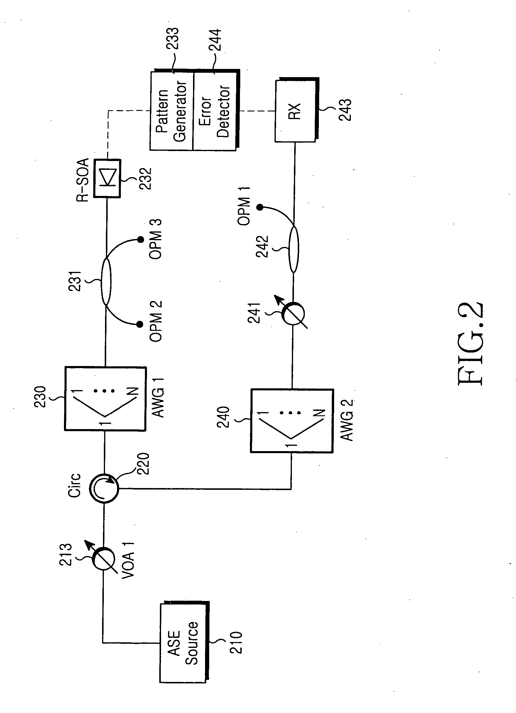
[0017]FIG. 2 is a block diagram illustrating a test apparatus for testing the quality of communication when a multiplexer / demultiplexer demultiplexes a central wavelength of multiplexed optical signals in order for the central wavelength of each multiplexed optical signal to be offset by a known amount according to an embodiment of the present invention. FIG. 3 is a graph for showing change in loss depending on offset of the central wavelength after demultiplexing as a result of a test using the test apparatus shown in FIG. 2.

[0018] The test apparatus shown in FIG. 2 includes a broadband light source 210 for generating light having a broad wavelength b...


PUM


Abstract

Disclosed is a passive optical network comprising a central office including a plurality of first reflective semiconductor optical amplifiers of a quantum-dot type, each of which generates a wavelength-seeded downstream optical signal on a downstream channel of a corresponding wavelength, a plurality of optical network units each of which includes a second reflective semiconductor optical amplifier of a multi-quantum-well type, the second reflective semiconductor optical amplifier generating a wavelength-seeded upstream optical signal on an upstream channel of a corresponding wavelength and a remote node for outputting the downstream optical signals to corresponding optical network units, and multiplexing and outputting the upstream optical signals to the central office.

Description

CLAIM OF PRIORITY [0001] This application claims to the benefit of the earlier filing date, pursuant to 35 U.S.C. 119(a), of that patent application entitled “Passive Optical Network,” filed in the Korean Intellectual Property Office on Dec. 1, 2004 and assigned Serial No. 2004-99906, the entire contents of which are incorporated herein by reference. BACKGROUND OF THE INVENTION [0002] 1. Field of the Invention [0003] The present invention relates to a passive optical network, and more particularly to a passive optical network including a light source which can generate wavelength-seeded optical signals. [0004] 2. Description of the Related Art [0005] Passive optical networks, generally, include a central office for providing a communication service, a plurality of optical network units for receiving the communication service, and at least one remote node for relaying the communication service between the central office and the optical network units. The central office and the remote...

Claims


Application Information

Patent Timeline
Patent Type & Authority Applications(United States)
IPC IPC(8): H04J14/00H04B10/00H04B10/2507H04B10/27H04B10/272
CPCB82Y10/00H04B10/2587H04B10/272H04J14/0226H04J14/0227H04J14/0282H04J14/0246H04J14/025H04J2014/0253H04B10/25
Inventor SHIN, HONG-SEOKHEO, DU-CHANGSHIM, CHANG-SUPHWANG, SEONG-TAEK
Owner SAMSUNG ELECTRONICS CO LTD
Why Eureka
Try Eureka