Method and device for treatment of mitral insufficiency

a technology for mitral insufficiency and mitral valve, which is applied in the field of mitral insufficiency devices, can solve the problems of biological prostheses suffering from limited durability, mechanical valves carries the risk of thromboembolism, and create insufficiency, and achieves the effect of reducing the overall length of the devi

Inactive Publication Date: 2006-06-01
EDWARDS LIFESCIENCES AG
View PDF88 Cites 109 Cited by
  • Summary
  • Abstract
  • Description
  • Claims
  • Application Information

AI Technical Summary

Benefits of technology

[0014] It is another object of the present invention to provide a treatment for mitral insufficiency that minimizes trauma to a patient's vasculature while using catheter based technology.
[0015] These and other objects of the present invention are achieved by providing a device for treatment of mitral insufficiency, whereby the circumference of the mitral valve annulus is reduced when the device is deployed and / or actuated in at least a portion of the coronary sinus.
[0017] In one embodiment comprising multiple components, the device comprises proximal and distal stent sections, wherein the proximal stent section comprises a deployable flange. The stent sections are delivered into the coronary sinus in a contracted state, and then are deployed within the coronary venous vasculature so that the flange engages the coronary sinus ostium. A cinch mechanism, comprising, for example, a plurality of wires and eyelets, is provided to reduce the distance between proximal and distal stent sections, thereby reducing the circumference of the mitral valve annulus.
[0020] The configuration of cells of the stent also may be varied to encourage the stent to assume a convex shape upon deployment. For example, one side of the stent may be configured to expand a greater amount than the other side, thereby imparting a convex curvature upon the stent. To facilitate proper positioning of the stent within the coronary sinus, an intravascular ultrasound transducer or radiopaque marker bands may be used to align the correct side of the stent adjacent the mitral valve annulus.
[0022] A yet further alternative embodiment comprises a series of linked segments that are capable of relative rotational and telescoping movement. In a preferred embodiment, each segment includes a ball element that couples to a socket element on an adjacent segment. The ball and socket connections permit the segments of the device to become angled relative to one another so that the device is capable of assuming a three-dimensional curvature. A cinch wire extends through a passage in the segments and permits the device to be cinched rigidly into a predetermined shape. Some segments also may include telescoping joints that permit the overall length of the device to be reduced upon actuation of the cinch wire. The cinch wire may include either a locking mechanism attached to the cinch wire or alternatively may include striations on the contacting ball and socket surfaces that permit the segments to rigidly engage one another when cinched.

Problems solved by technology

Any one or all of these in different combinations may be injured and create insufficiency.
The mechanical valve carries the risk of thromboembolism and requires anticoagulation, with all its potential hazards, whereas biological prostheses suffer from limited durability.
Another hazard with replacement is the risk of endocarditis.
To certain groups of patients, this is particularly hazardous.

Method used


Image

  • Method and device for treatment of mitral insufficiency
  • Method and device for treatment of mitral insufficiency
  • Method and device for treatment of mitral insufficiency

Examples


Embodiment Construction

[0039] The present invention takes advantage of the position of the coronary sinus being close to the mitral annulus. This makes repair possible by the use of current catheter-guided techniques by deploying one element in the coronary venous vasculature that applies a load to, and reshapes, the adjacent posterior portion of the mitral annulus.

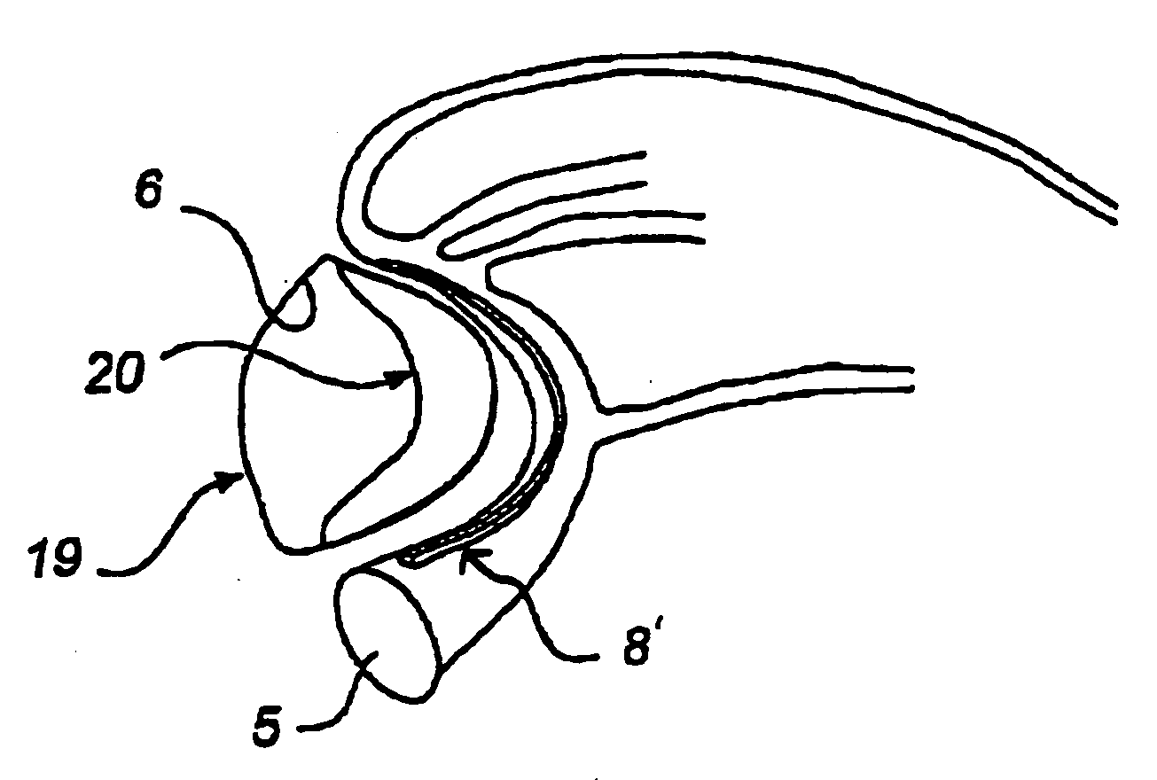
[0040] The coronary veins drain blood from the myocardium to the right atrium. The smaller veins drain blood directly into the atrial cavity, and the larger veins accompany the major arteries and run into the coronary sinus which substantially encircles the mitral orifice and annulus. The coronary sinus runs in the posterior atrioventricular groove, lying in the fatty tissue between the left atrial wall and the ventricular myocardium, before draining into the right atrium between the atrial septum and the post-Eustachian sinus.

[0041]FIG. 1 is a cross-sectional view through the heart area of posterior atrioventricular groove 1, which is filled...


PUM

PropertyMeasurementUnit
distanceaaaaaaaaaa
circumferenceaaaaaaaaaa
shape memoryaaaaaaaaaa

Abstract

A device for treatment of mitral annulus dilation is disclosed, wherein the device comprises two states. In a first of these states the device is insertable into the coronary sinus and has a shape of the coronary sinus. When positioned in the coronary sinus, the device is transferable to the second state assuming a reduced radius of curvature, whereby the radius of curvature of the coronary sinus and the radius of curvature as well as the circumference of the mitral annulus is reduced.

Description

REFERENCE TO RELATED APPLICATIONS [0001] The present application is a continuation of U.S. patent application Ser. No. 10 / 329,720, filed Dec. 24, 2002, which is a continuation-in-part of U.S. patent application Ser. No. 09 / 775,677, filed Feb. 5, 2001, which is a continuation-in-part of U.S. patent application Ser. No. 09 / 345,475, filed Jun. 30, 1999, now U.S. Pat. No. 6,210,432. U.S. patent application Ser. No. 10 / 329,720 also claims the benefit under 35 U.S.C. §119 to U.S. provisional application Ser. No. 60 / 344,121, filed Dec. 28, 2001. Each of the referenced applications is hereby incorporated by reference in its entirety.FIELD OF THE INVENTION [0002] The present invention relates to a device for treatment of mitral insufficiency and, more specifically, for treatment of dilation of the mitral annulus. BACKGROUND OF THE INVENTION [0003] Mitral insufficiency can result from several causes, such as ischemic disease, degenerative disease of the mitral apparatus, rheumatic fever, endo...

Claims


Application Information

Patent Timeline
Patent Type & Authority Applications(United States)
IPC IPC(8): A61F2/24A61F2/02A61F2/26A61F2/82A61F2/88A61F2/90
CPCA61F2/07A61F2/2451A61F2/88A61F2/90A61F2/91A61F2002/826A61F2002/828A61F2002/8483A61F2210/0004
Inventor SOLEM, JAN OTTOKIMBLAD, PER-OLAOEPEN, RANDOLF VONQUINT, BODOSEIBOLD, GERDMICHLITSCH, KENNETH J.HA, SUK-WOOECKERT, KARL-LUDWIGJOERGENSEN, IBNIELSEN, STEVAN
Owner EDWARDS LIFESCIENCES AG
Why Eureka
Try Eureka