Spray cooling with spray deflection

a technology of spray cooling and spray deflection, which is applied in the direction of domestic cooling apparatus, semiconductor/solid-state device details, lighting and heating apparatus, etc., to achieve the effect of efficient operation

Active Publication Date: 2006-06-08
HEWLETT-PACKARD ENTERPRISE DEV LP
View PDF31 Cites 15 Cited by
  • Summary
  • Abstract
  • Description
  • Claims
  • Application Information

AI Technical Summary

Benefits of technology

[0018] In various embodiments, the present invention solves some or all of the needs mentioned above by providing a package-level cooling system that efficiently operates to provide accurate cooling to a component.

Problems solved by technology

The system may further feature an obstruction such as a gutter configured to obstruct cooling fluid sprayed in one of the directions from striking the component.

Method used


Image

  • Spray cooling with spray deflection
  • Spray cooling with spray deflection
  • Spray cooling with spray deflection

Examples


first embodiment

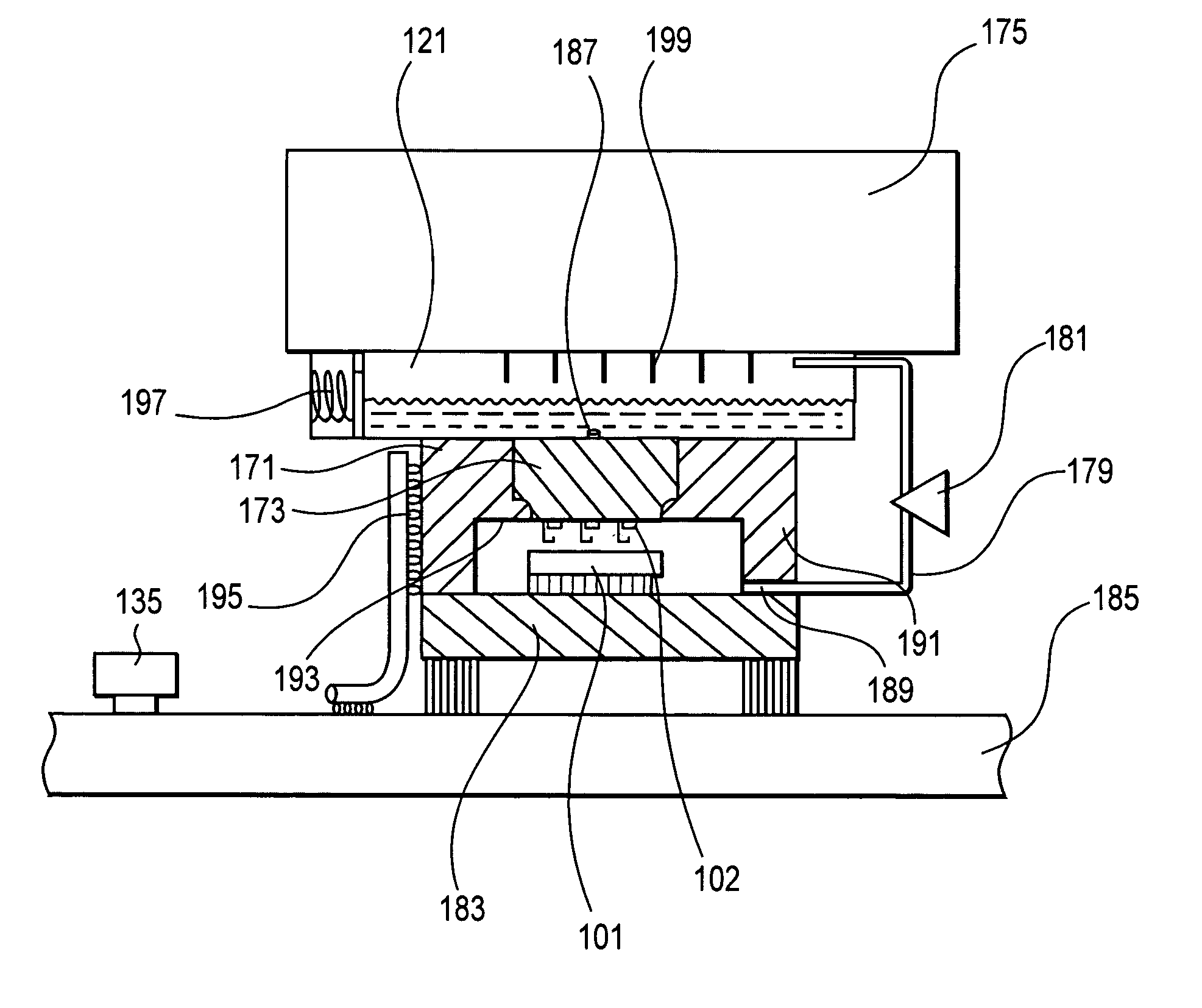
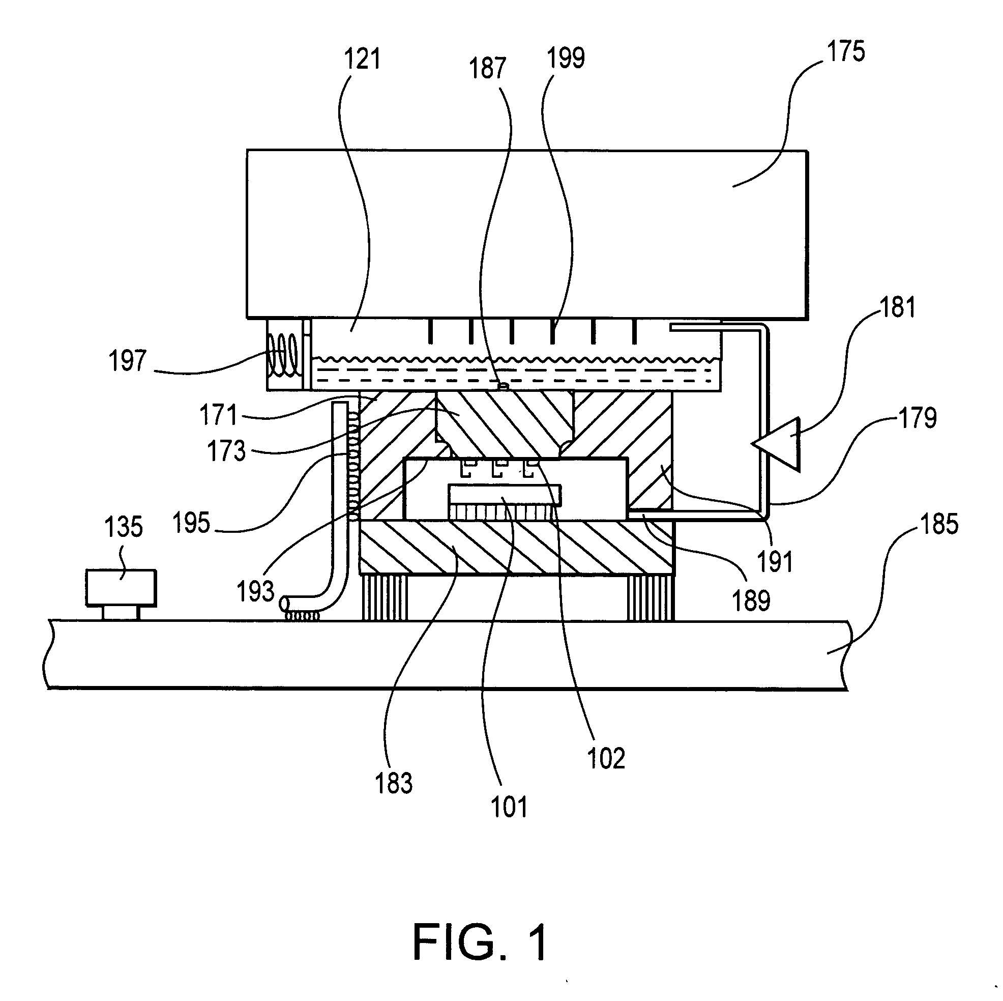
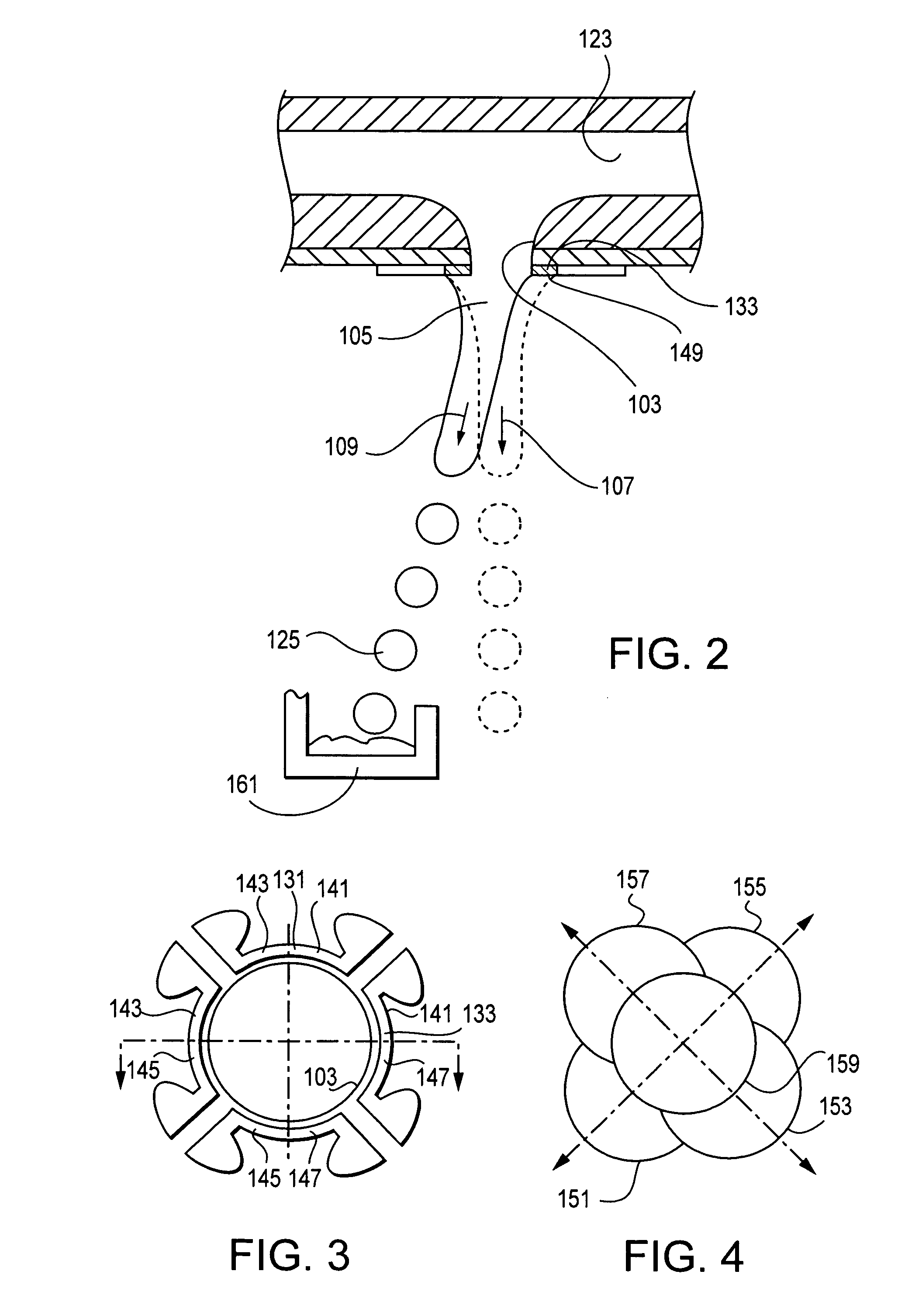
[0034] With reference to FIGS. 1-3, a cooling system is for cooling a component 101, such as a heat-generating semiconductor device, other information processing device, optical component, or the like. The system cools the component by spraying the component with a cooling fluid. The system includes a plurality of sprayers 102, each sprayer having an orifice 103 configured to eject a stream 105 of the cooling fluid. The system also includes a stream deflector operable to selectively control deflection of the stream between spraying in an undeflected direction 107 and spraying in a deflected direction 109, where the undeflected direction is preferably in an unobstructed direction toward the component. The deflector is preferably integrated into the silicon of the sprayer using standard MEMs manufacturing precesses.

[0035] The sprayers are provided with cooling fluid from a reservoir 121 containing pressurized cooling fluid. The reservoir is in fluid communication with a cooling fluid ...

third embodiment

[0074] Similar to the first two embodiments, the cooling system preferably has a plurality of sprayers. Optionally, the plurality of sprayers includes a first sprayer and a second sprayer configured to provide redundancy, flexibility in operation, and / or additional cooling capability by each having a spray direction toward a single thermal location on the component. Preferably, each sprayer has at least two different spray locations on the component, not all of witch overlap with the locations of the other sprayer. The controller is configured to control operation of the first and second sprayer's stream deflectors to provide the redundancy, flexibility in operation, or additional cooling capability. As with the first two embodiments, sprayers could have overlapping spray locations with a plurality of neighboring sprayers to provide additional redundancy.

[0075] With reference to FIG. 8, a fourth embodiment of a cooling system is similar to the first through third embodiments, but th...

second embodiment

[0080] The control surface 449 causes a deflection of the stream with respect to the streams natural (undeflected) direction. This deflection, which is related to the gain in free energy caused by the contact, and could also be influenced by interference with the stream's flow, may be controlled by controlling the location of the control surface with respect to the stream. Optionally, this control surface location may be adjusted longitudinally along the flow direction of the stream, and / or laterally across the flow direction of the stream. The stream deflector thus optionally includes a moveable control surface configured to contact the stream, which is conceptually similar to that of the

[0081] The covering layer 447 is composed of an electrically insulating material that prevents the flow of electricity between the stream 405 and the second electrode 443. The covering layer is preferably thin (e.g., a thin coating), to allow the potential between the stream and the second electrod...


PUM


Abstract

A component cooling system including a sprayer configured to eject a stream of cooling fluid and a stream deflector to control deflection of the stream. The sprayer may be continuous or incremental. Excess spray may be deflected into a gutter configured to obstruct cooling fluid from striking the component. The stream deflector may operate using a contact surface, controllable orifice heaters, and / or electrodes is configured to deflect the stream in one or more degrees of freedom. Multiple sprayers may have overlapping spray patterns for redundancy.

Description

[0001] The present invention relates generally to cooling systems for heat-generating devices and, more particularly, to a spray cooling system and a method of using the spray cooling system to cool one or more semiconductor devices (i.e., chips). BACKGROUND OF THE INVENTION [0002] With the advent of semiconductor devices having increasingly large component densities, the removal of heat generated by the devices has become an increasingly challenging technical issue. Over time, the frequency of operation of CMOS devices has increased significantly. The resulting microprocessor power dissipation has likewise gone up by an order of magnitude. While the input voltage and capacitance of devices has decreased, the number of devices on a typical microprocessor die continues to increase rapidly as processing efficiency is sought. Moreover, device miniaturization has led device designers to integrate previously separate components, such as those used to create a cache, into the microprocess...

Claims


Application Information

Patent Timeline
Patent Type & Authority Applications(United States)
IPC IPC(8): F28C1/00F28D3/00F25D23/12F28D5/00
CPCF28D5/00H01L23/4735H01L2224/16H01L2924/1461H01L2924/00H01L2924/00014H01L2924/00011H01L2224/0401
Inventor BASH, CULLEN E.PATEL, CHANDRAKANT D.
Owner HEWLETT-PACKARD ENTERPRISE DEV LP
Why Eureka
Try Eureka