Hydrogen vehicle gas utilization and refueling system

a hydrogen vehicle and gas utilization technology, applied in the direction of fluid pressure control, transportation items, packaged goods, etc., can solve the problems of failing vehicles not being able to receive full filling, hydrogen in those banks cannot be utilized, and mechanical energy loss in hydrogen refilling systems, so as to reduce the compression energy required to refill the tank, the effect of minimizing mechanical energy loss

Inactive Publication Date: 2006-06-08
HONDA MOTOR CO LTD
View PDF2 Cites 55 Cited by
  • Summary
  • Abstract
  • Description
  • Claims
  • Application Information

AI Technical Summary

Benefits of technology

[0006] It is an object of the present invention to minimize mechanical energy loss in hydrogen refilling systems when factored into the overall energy efficiency of an infrastructure of hydrogen powered vehicles and fuel depots. Each time a vehicle is refueled with hydrogen, energy is required to compress the hydrogen into the vehicle's tanks, hence, it is an object of the invention to minimize the compression energy required to refill an on board fuel storage tank in a hydrogen powered motor vehicle. It is a further object of the invention to provide a system whereby, one tank at a time, hydrogen is withdrawn from and refilled into multiple tanks, thereby reducing the compression energy required to refill the tanks.
[0007] On the refueling station side where the hydrogen station has a limited supply of hydrogen available to fill multiple vehicles, and where a hydrogen station uses the multiple bank cascade fill strategy described above, when the vehicle's tank pressure is greater than any of the station bank pressures, the banks at the station cannot be used to fill the vehicle, and the hydrogen in those banks cannot be utilized. Thus, only banks with pressure higher than that of the vehicle tank(s) are used, depleting the pressure in the banks of higher pressure tanks, resulting in a situation where a succeeding vehicle may not be able to receive a full fill. Using the system described herein, it is an object to enhance the ability of a refilling station to service the fuel needs of hydrogen powered vehicles. The invention also provides a system for evacuating hydrogen from multiple high pressure storage tanks on a vehicle for the purpose of maximizing well to tank energy efficiency.
[0008] Currently, all valves on a vehicle with multiple hydrogen storage tanks are opened simultaneously by a control system allowing each tank to contribute equally to supply hydrogen to the fuel cell stack or internal combustion engine. The current technology, however, does not maximize the well to tank energy efficiency of the vehicle or the utilization of the limited supply of hydrogen at a hydrogen filling station. The invention decreases the energy lost to compression of the hydrogen, which results in a higher well to tank efficiency, thus providing a benefit to the environment, to the station provider, and to the vehicle owner. In addition, the invention increases the amount of utilizable hydrogen at a hydrogen station with limited storage capacity. In the invention, the pressure in the vehicle tank(s) is minimized, allowing the hydrogen in the lower pressure banks at the hydrogen station to be used, resulting in better utilization of the limited hydrogen stored at the station.

Problems solved by technology

On the refueling station side where the hydrogen station has a limited supply of hydrogen available to fill multiple vehicles, and where a hydrogen station uses the multiple bank cascade fill strategy described above, when the vehicle's tank pressure is greater than any of the station bank pressures, the banks at the station cannot be used to fill the vehicle, and the hydrogen in those banks cannot be utilized.
Thus, only banks with pressure higher than that of the vehicle tank(s) are used, depleting the pressure in the banks of higher pressure tanks, resulting in a situation where a succeeding vehicle may not be able to receive a full fill.
The current technology, however, does not maximize the well to tank energy efficiency of the vehicle or the utilization of the limited supply of hydrogen at a hydrogen filling station.

Method used


Image

  • Hydrogen vehicle gas utilization and refueling system
  • Hydrogen vehicle gas utilization and refueling system
  • Hydrogen vehicle gas utilization and refueling system

Examples


Embodiment Construction

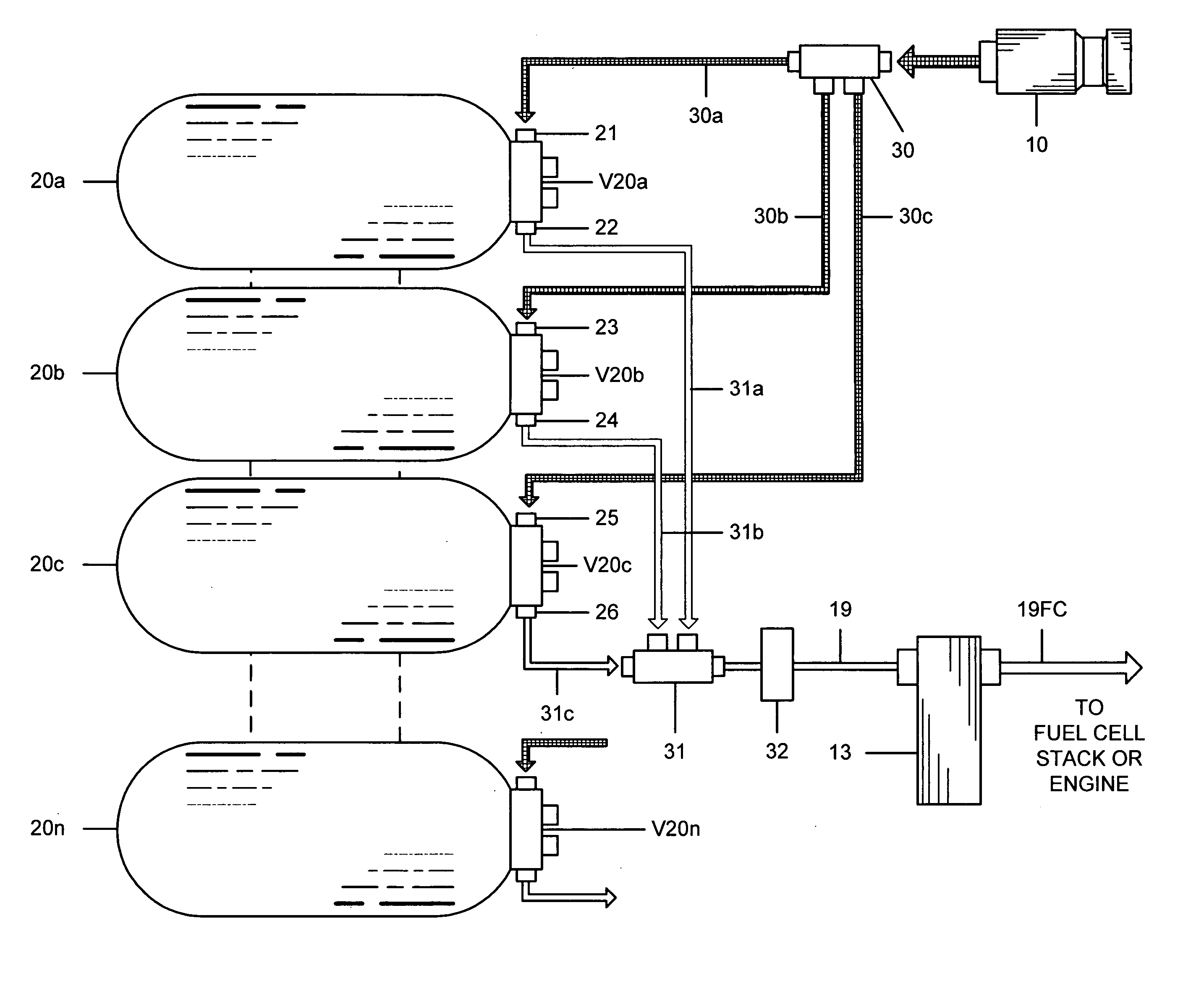
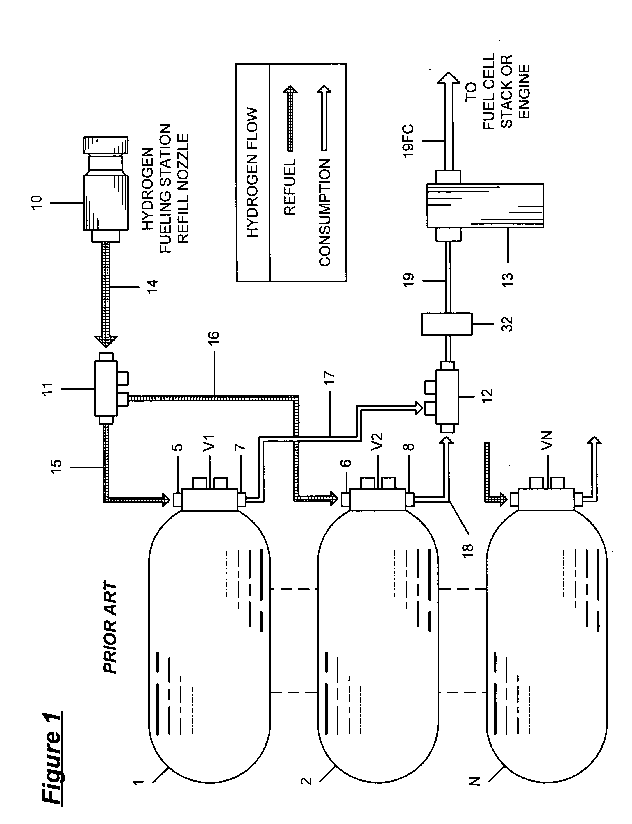
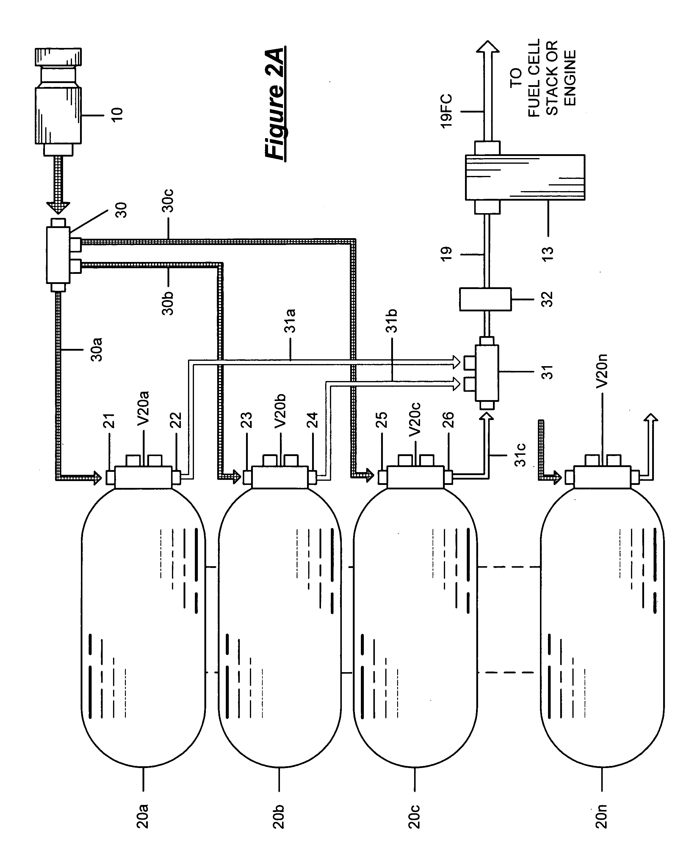
[0018] The system of the invention increases the refueling energy efficiency of hydrogen powered vehicles by withdrawing hydrogen from one tank, in the bank of multiple on board storage tanks, at a time, until a cut off or threshold minimum pressure is reached. When the threshold cut off pressure is reached in a tank in use, the next tank in sequence is opened to allow gas flow from the next tank to the fuel cell or engine. This process is repeated for all tanks on the vehicle. In the overall vehicle / refueling station system, when the vehicle is refueled with hydrogen, less compression energy is required to refill the tanks. The invention increases the total energy efficiency from well to tank and increases hydrogen station gas utilization by utilizing more efficiently the limited quantity of hydrogen at the filling station and by reducing the energy required to compress the hydrogen at the station (or to the vehicle directly) back to a full state after refueling. The invention cons...


PUM

PropertyMeasurementUnit
pressureaaaaaaaaaa
pressureaaaaaaaaaa
pressureaaaaaaaaaa

Abstract

A system for increasing the overall efficiency of a hydrogen fueled vehicle and refilling station infrastructure wherein the process of (1) consuming pressurized hydrogen gas that is stored in on board tanks used to power hydrogen fueled motor vehicles and (2) refueling the vehicle tanks at a hydrogen refilling station after the available on board fuel supply in the tanks is consumed is controlled according to a predetermined sequence involving the utilization of the hydrogen in the on board tanks.

Description

FIELD OF THE INVENTION [0001] The present invention relates to a system for efficiently evacuating and refueling hydrogen gas from and into multiple high pressure storage tanks such as used on board in motor vehicles and in larger quantities at hydrogen storage and refueling stations. BACKGROUND OF THE INVENTION [0002] When hydrogen is used as a fuel in motor vehicles, a hydrogen fuel depot infrastructure for refueling must also be developed. Typically, in the use of hydrogen to power fuel cells or internal combustion engines in motor vehicles, hydrogen is stored in on board fuel tanks maintained at a maximum pressure in the range of about 5000 psi. In the instance of a fuel cell powered vehicle, utilization of the hydrogen input into the fuel cell stack occurs at about 30 psi. The consumption and evacuation of hydrogen from on board fuel tanks to power a vehicle having a fuel cell or internal combustion engine should smoothly correlate with a motor vehicle operator's desire for on ...

Claims


Application Information

Patent Timeline
Patent Type & Authority Applications(United States)
IPC IPC(8): F17D1/00
CPCB60K15/00F17C2270/0184F17C5/04F17C2227/043G05D16/2046G05D16/206Y02E60/321F17C2201/0109F17C2201/054F17C2205/0134F17C2205/0326F17C2205/0335F17C2205/0338F17C2221/012F17C2223/0123F17C2223/036F17C2250/043F17C2250/0439F17C2250/0636F17C2250/072F17C2260/026F17C2265/065F17C2270/0139F17C2270/0168B60K2015/0319Y10T137/6855Y10T137/469Y02E60/32
Inventor MATHISON, STEVEN R.MATSUO, SHIRO
Owner HONDA MOTOR CO LTD
Why Eureka
Try Eureka