Water cooling system for computer components

Inactive Publication Date: 2006-06-08
STAFFORD ERIC
View PDF20 Cites 23 Cited by
  • Summary
  • Abstract
  • Description
  • Claims
  • Application Information

AI Technical Summary

Benefits of technology

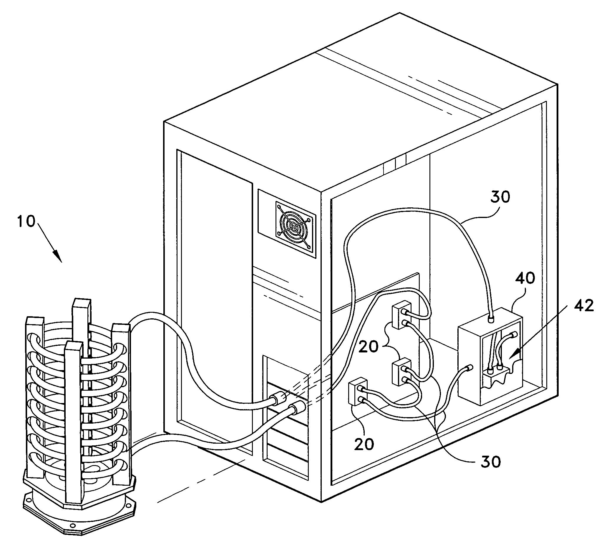
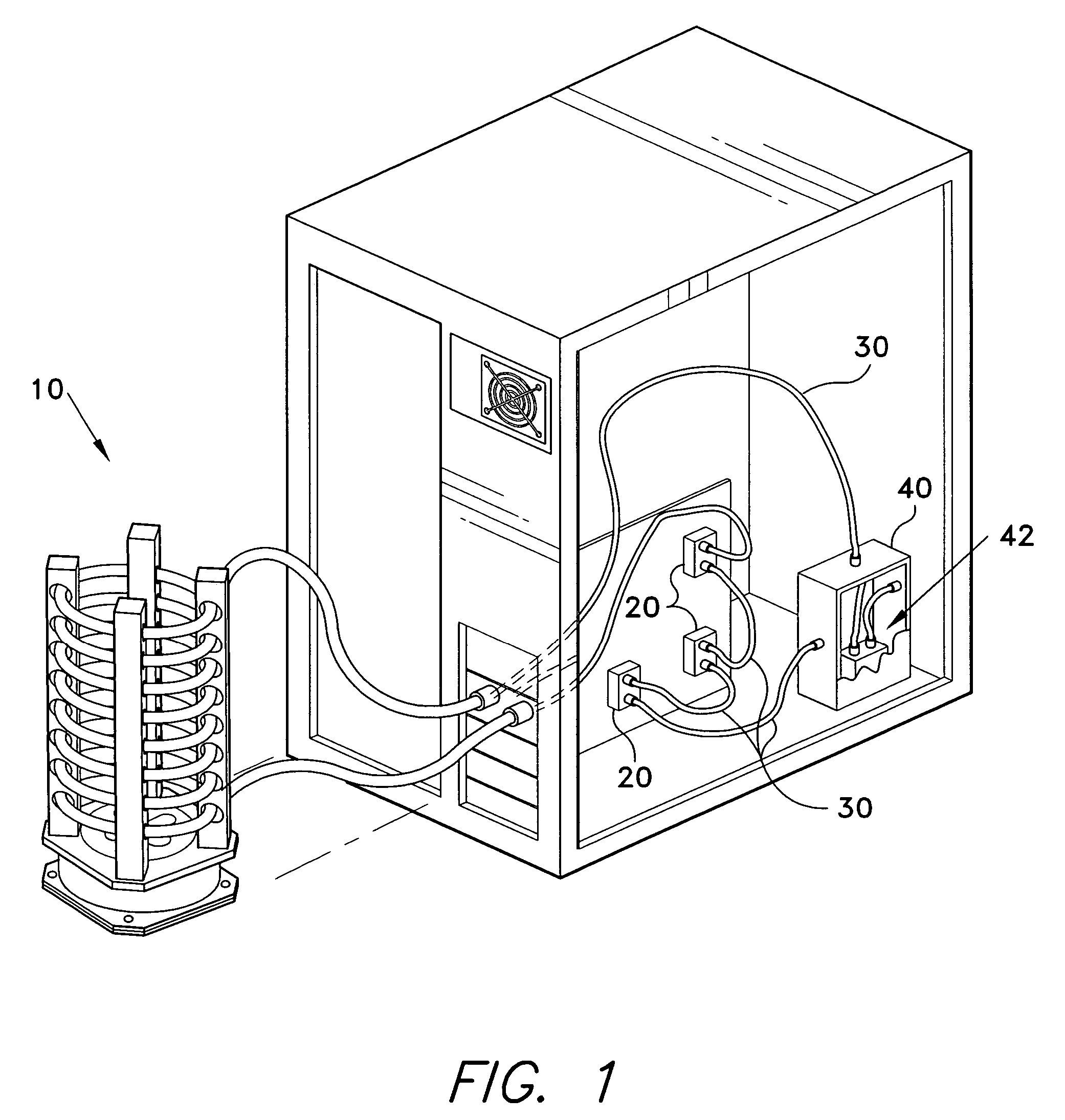
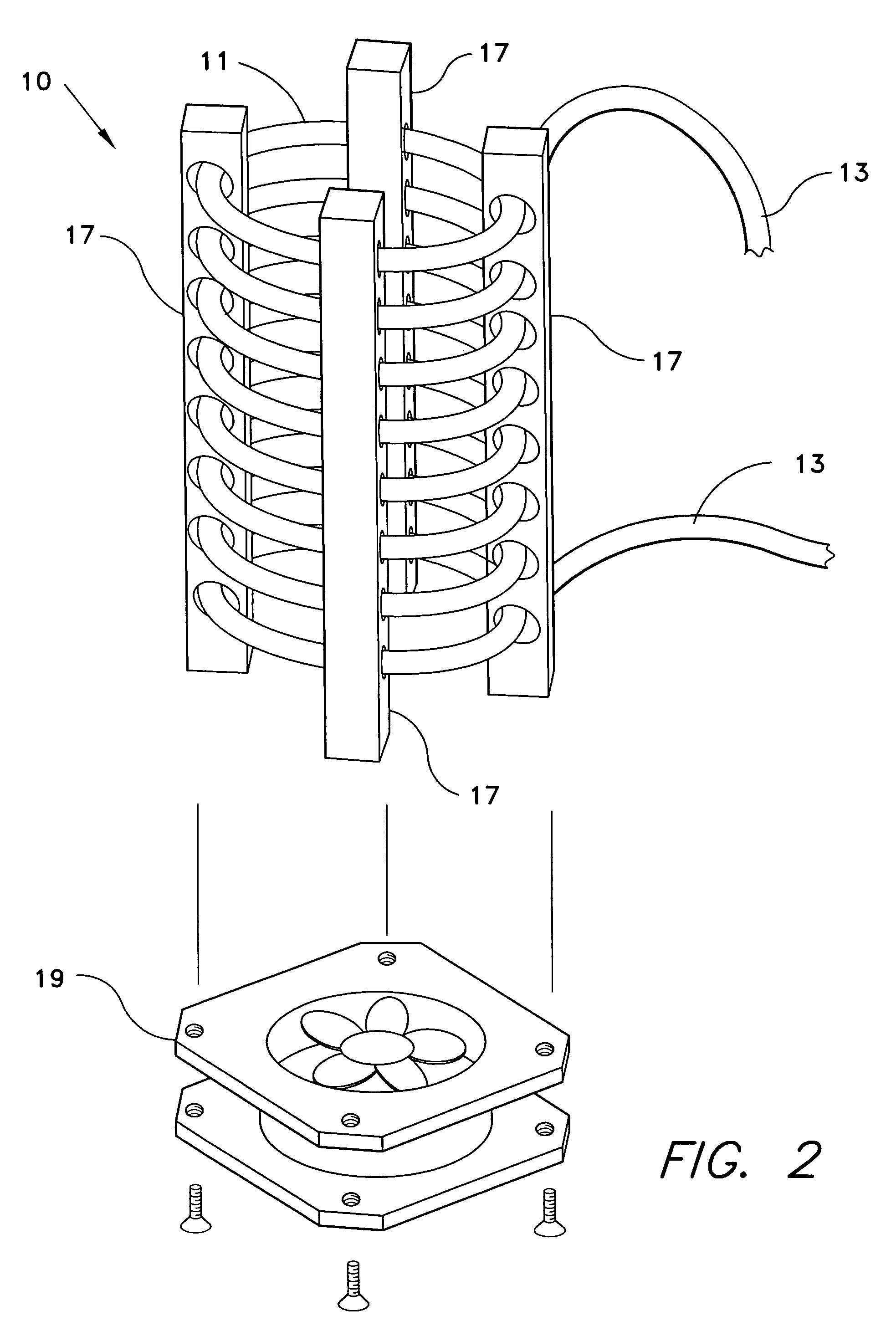
[0010] The water cooling system for computer components employs a heat-dissipating device along with one or more water blocks to cool electronic components of a computer system. The water cooling system for computer components employs, as a heat dissipating device, a length of copper tubing formed into a coil. The copper coil provides sufficient heat transfer for the cooling system with no fans employed. A single fan may be used to pass air over the coiled tubing for enhanced heat dissipation, the fan being oriented to move air along an axis passing lengthwise through the coil.

Problems solved by technology

Over-temperature operations can lead to decreased performance and to component damage.
While such a technique can be effective, such a generalized cooling may be insufficient for a circuit where one or a few individual components produce the greatest amount of heat.
With such single-point sources of heat, generalized airflow within the computer housing does not provide optimal cooling.
Size considerations, as well as practical limitations on the amount of air that can be circulated within the housing, limit the effectiveness of air-cooled heat sinks.
A water channel passing through the water block is subject to manufacturing limitations, and thus may not be optimally routed to direct the cooling water to the center of the circuit component, where heat production is greatest.
In this case, placement of a water channel is limited by the reach of a drill press.
While this method allows an arbitrary water channel path, the need to seal the cover presents an increased risk of leakage.
Increasing the number, and thereby the density, of the cooling fins tends to require additional, or stronger, fans to force ail through the decreased spaces between fins, and thus increase the noise and vibration produced by the cooling system, as well as the power required to operate the cooling system.
Additionally, suitable radiators tend to be relatively costly.

Method used


Image

  • Water cooling system for computer components
  • Water cooling system for computer components
  • Water cooling system for computer components

Examples


embodiment 100

[0028] Turning now to FIGS. 4 and 5, an embodiment 100 of a water-block heat exchanger 20 for a computer system's CPU is shown. The CPU water-block 100 is formed from a single piece, solid block 110 of a metal such as aluminum or copper, or another material having a suitable heat-conducting property, the block 110 being generally square and having dimensions compatible with a computer CPU such as the Pentium© processor made by Intel©. A water channel 120 is formed within the block 110 by drilling a several interconnecting holes into the block 110. The block 110 is a square block having four sides 111, 111B, 111C and 111D, a top surface 113 and a bottom surface 115. Corners 117 of the block are beveled to assist in aligning the mounting bracket 25 with the block 110.

[0029] The water channel 120 comprises a first hole 121 drilled into a side 111A of the block 110, and extending substantially, but not completely, through the block 110. The first hole 121 lies adjacent and parallel to t...

embodiment 200

[0031] Turning now to FIGS. 7 and 8, an embodiment 200 of a water-block heat exchanger 20 for a computer system's VGA chip is shown. The VGA water-block 200 is formed from a solid block 210 of a metal such as aluminum or copper, or another material having a suitable heat-conducting property, the block 210 being generally square and having dimensions compatible with a typical computer system VGA chip. A water channel 220 is formed within the VGA water-block 200 by drilling a several interconnecting holes into the block 210. The block 210 is a generally square block having four sides 211A, 211B, 211C and 211D, a top surface 213 and a bottom surface 215. Opposing corners of the block 210 are beveled to form opposing corner faces 217.

[0032] The water channel 220 comprises a first hole 221 drilled into one of the corner faces 217, and extending diagonally through the block 210, passing through the center of the block 210. The first hole 221 may extend entirely through the block, exiting ...


PUM


Abstract

The water cooling system for computer components is a system for removing heat from the heat-producing components of a computer, or other electronic, system. The water cooling system for computer components employs one or more water-block type heat exchangers to remove heat from electronic circuit components, transferring heat to a fluid coolant. A heat dissipating device, in the form of a tubing coil, dissipates heat from the coolant. A coolant pump circulates a fluid coolant from a coolant reservoir, through fluid conduits interconnecting the water-block heat exchangers and the heat dissipating device. The water-block type heat exchangers are formed from a single, solid block of material, and have an internal water passage directing the fluid coolant through the center of the block to apply maximum cooling to the center of an electronic circuit components where the maximum heat is produced.

Description

BACKGROUND OF THE INVENTION [0001] 1. Field of the Invention [0002] The present invention relates to a cooling system for electronic components, and more particularly, to a water cooling system for computer components components. [0003] 2. Description of the Related Art [0004] It is well known that electronic components generate heat during operation. Integrated circuit components tend to generate an increasing amount of heat as additional circuits or gates are included in ever-smaller packages. In computer systems, including well-known personal computer systems, generated heat must be removed from the electronic components to maintain the system within operating limits. Over-temperature operations can lead to decreased performance and to component damage. [0005] In computer systems, including personal computers, fans are commonly used to circulate air over the electronic components for cooling. One or more fans typically draws air into the computer's housing, providing a general co...

Claims


Application Information

Patent Timeline
IPC IPC(8): F28D15/00
CPCF28D1/024F28D1/0472F28F7/02G06F1/20G06F2200/201H01L2924/0002H01L23/473H01L2924/00
Inventor STAFFORD, ERIC
Owner STAFFORD ERIC
Why Eureka
Try Eureka