Evaporator and refrigeration cycle

a technology of evaporator and refrigeration cycle, which is applied in the direction of indirect heat exchangers, refrigeration components, light and heating apparatus, etc., can solve the problems of requiring a correspondingly increased cost or additional space for installation, and the noise released by the evaporator which is provided at a relatively close position to the vehicle compartment will be unfavorable to the passenger, and achieves outstanding air cooling performan

Inactive Publication Date: 2006-06-08
SHOWA DENKO KK
View PDF13 Cites 6 Cited by
  • Summary
  • Abstract
  • Description
  • Claims
  • Application Information

AI Technical Summary

Benefits of technology

[0047] The refrigeration cycle attains outstanding air cooling performance since a reduction is achieved in the pressure loss to be involved in introducing the refrigerant into the multi-pass providing inner pipe installed within the evaporator or in discharging the refrigerant from the inner pipe.

Problems solved by technology

However, such noises are likely to occur in evaporators depending on the conditions involved in the flow of the refrigerant.
Especially in the case of motor vehicle air conditioners, noises released from the evaporator which is provided at a position relatively close to the vehicle compartment will be disagreeable to the passenger.
These means use the sound absorbing material or muffler in addition to the usual components of the refrigeration cycle and will therefore require a correspondingly increased cost or additional space for installation.
If the diameter of the inlet channel is excessively larger than the inside diameter of the inner pipe, the flow of refrigerant involves an increased pressure loss, possibly failing to exhibit the contemplated air cooling performance.
If the diameter of the outlet channel is excessively greater than the inside diameter of the inner pipe, an increased refrigerant pressure loss will also result to entail impaired cooling performance.

Method used


Image

  • Evaporator and refrigeration cycle
  • Evaporator and refrigeration cycle
  • Evaporator and refrigeration cycle

Examples


Embodiment Construction

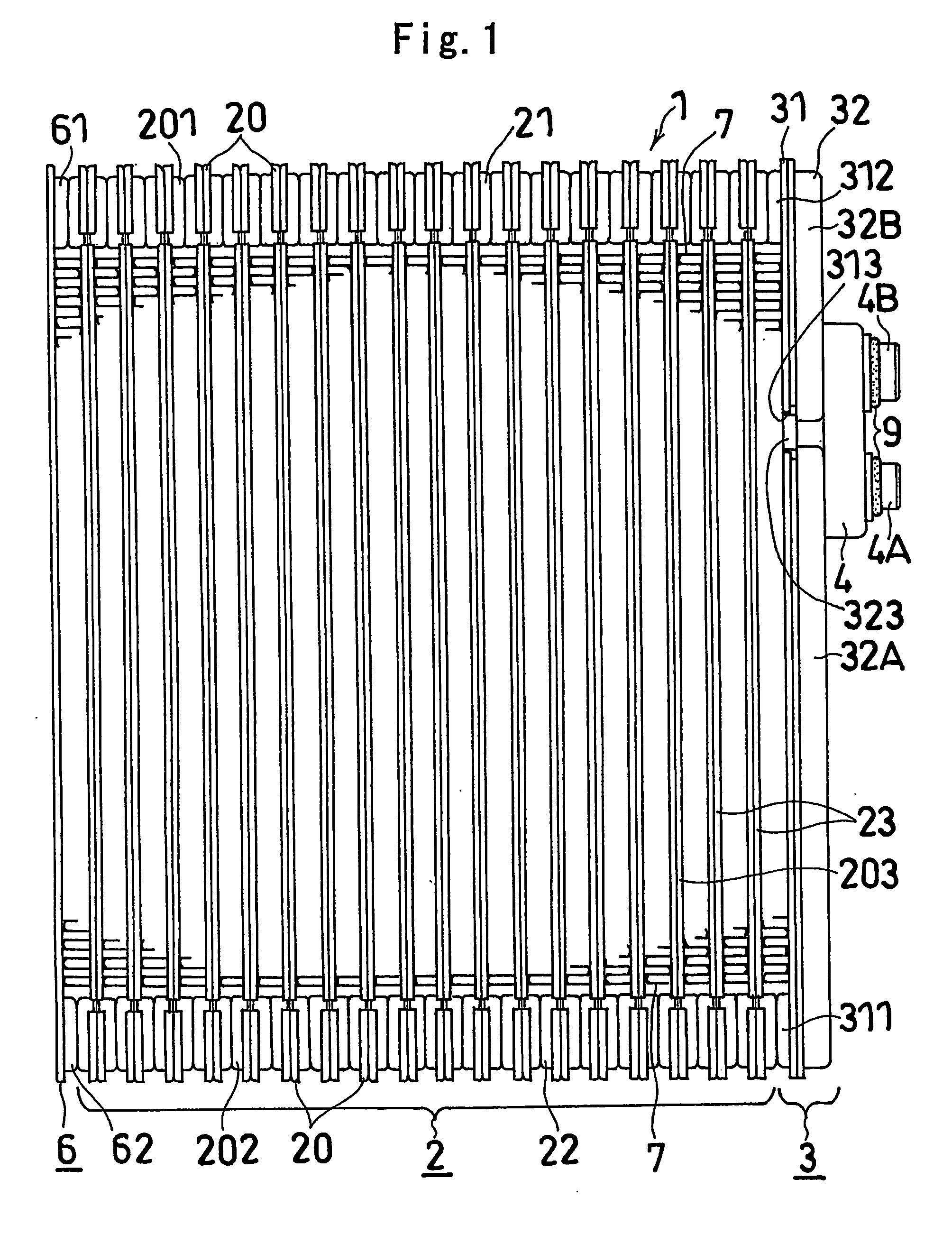
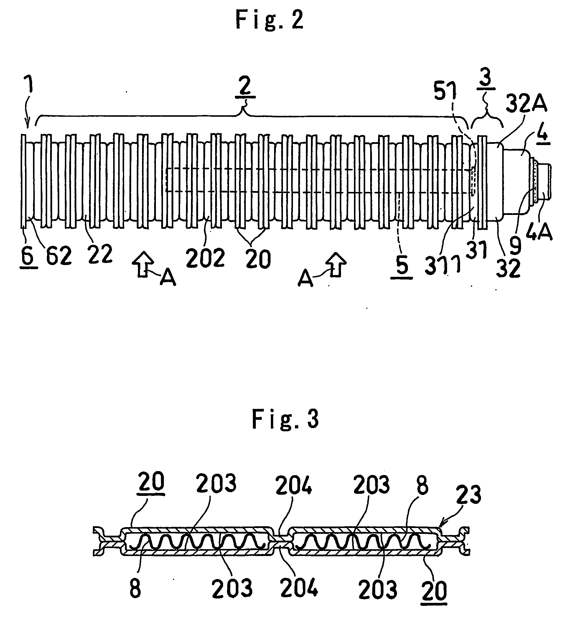
[0055] Next, the preferred embodiment of the invention will be described with reference to FIGS. 1 to 7. In the following description, the upper, lower, left-hand and right-hand sides of FIG. 1 will be referred to as “upper,”“lower,”“left” and “right,” respectively, and the upper side of FIG. 2 will be referred to as “front,” and the lower side of FIG. 2 as “rear.”

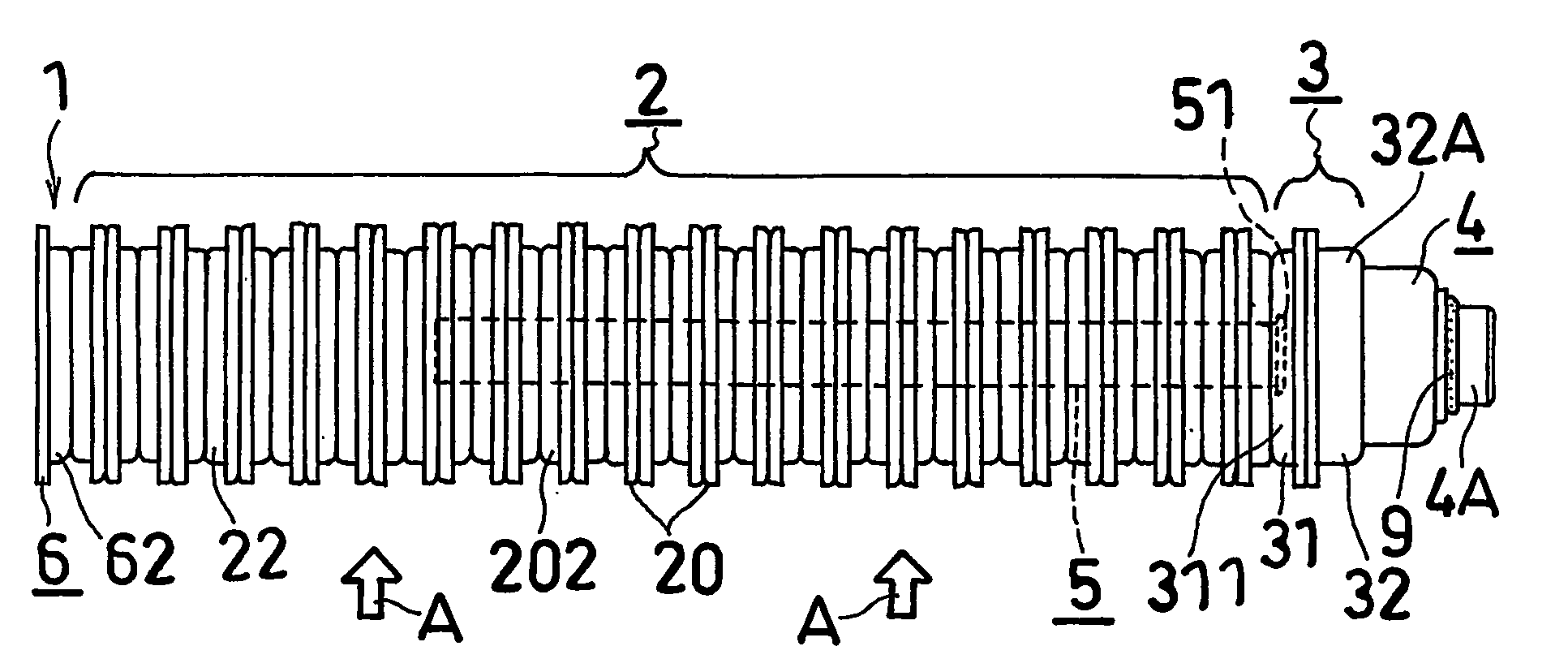
[0056] The embodiment is a layered evaporator embodying the present invention for use in motor vehicle air conditioners. With reference to FIGS. 1 and 2, the evaporator 1 of the invention comprises an evaporator core 2, and a connecting member 3 joined to the right side of the core 2. A pipe joint member 4 is joined to a right side portion of the connecting member 3. The evaporator 1 of this embodiment is made of aluminum (including an aluminum alloy), and brazing is usually resorted to for joining the components of the evaporator to be described below.

[0057] The evaporator core 2 comprises upper and lower two horizontal ...


PUM


Abstract

An evaporator including an evaporator core having a refrigerant inlet and a refrigerant outlet in one side portion thereof, and a connecting member joined to the side portion of the core and having in its interior a refrigerant inlet channel and a refrigerant outlet channel. The connecting member includes first and second plates. The second plate has an inlet channel recessed portion and an outlet channel recessed portion provided, each in the bottom wall thereof, with an inlet pipe connecting opening and an outlet pipe connecting opening, respectively. The first plate has on the outer surface thereof a refrigerant flow smoothing projection projecting toward the inlet pipe connecting opening. Refrigerant flowing into the inlet channel flows along the projection surface, thereby changes its flow direction smoothly and is less likely to produce a turbulent flow. The evaporator is therefore adapted to prevent occurrence of noises due to refrigerant flow.

Description

CROSS REFERENCE TO RELATED APPLICATIONS [0001] This application is an application filed under 35 U.S.C. §111(a) claiming the benefit pursuant to 35 U.S.C. §119(e)(1) of the filing date of Provisional Applications No. 60 / 363,244 and No. 60 / 363,369 both filed Mar. 12, 2002 pursuant to 35 U.S.C. §111(b).TECHNICAL FIELD [0002] The present invention relates to evaporators, for example, for use in motor vehicle air conditioners, and to motor vehicle air conditioners and like refrigeration cycles comprising the evaporator. BACKGROUND ART [0003] For example in refrigeration cycles such as motor vehicle air conditioners, noises made by the flow of refrigerant, such as a whistling noise and hissing noise, are produced mainly in condensers or expansion valves. However, such noises are likely to occur in evaporators depending on the conditions involved in the flow of the refrigerant. Especially in the case of motor vehicle air conditioners, noises released from the evaporator which is provided ...

Claims


Application Information

Patent Timeline
Patent Type & Authority Applications(United States)
IPC IPC(8): F28D1/02F25B39/02F28D1/03
CPCF25B39/022F28D1/0333F28D1/0341F28D2021/0085F28F9/027F28F2280/06F28F9/0253F28F9/0246
Inventor HANAFUSA, TATSUYA
Owner SHOWA DENKO KK
Why Eureka
Try Eureka