

Method and system for cooling an electrolytic cell for aluminum production
- Summary
- Abstract
- Description
- Claims
- Application Information
AI Technical Summary
Benefits of technology
Problems solved by technology
Method used
Image

Examples
Embodiment Construction
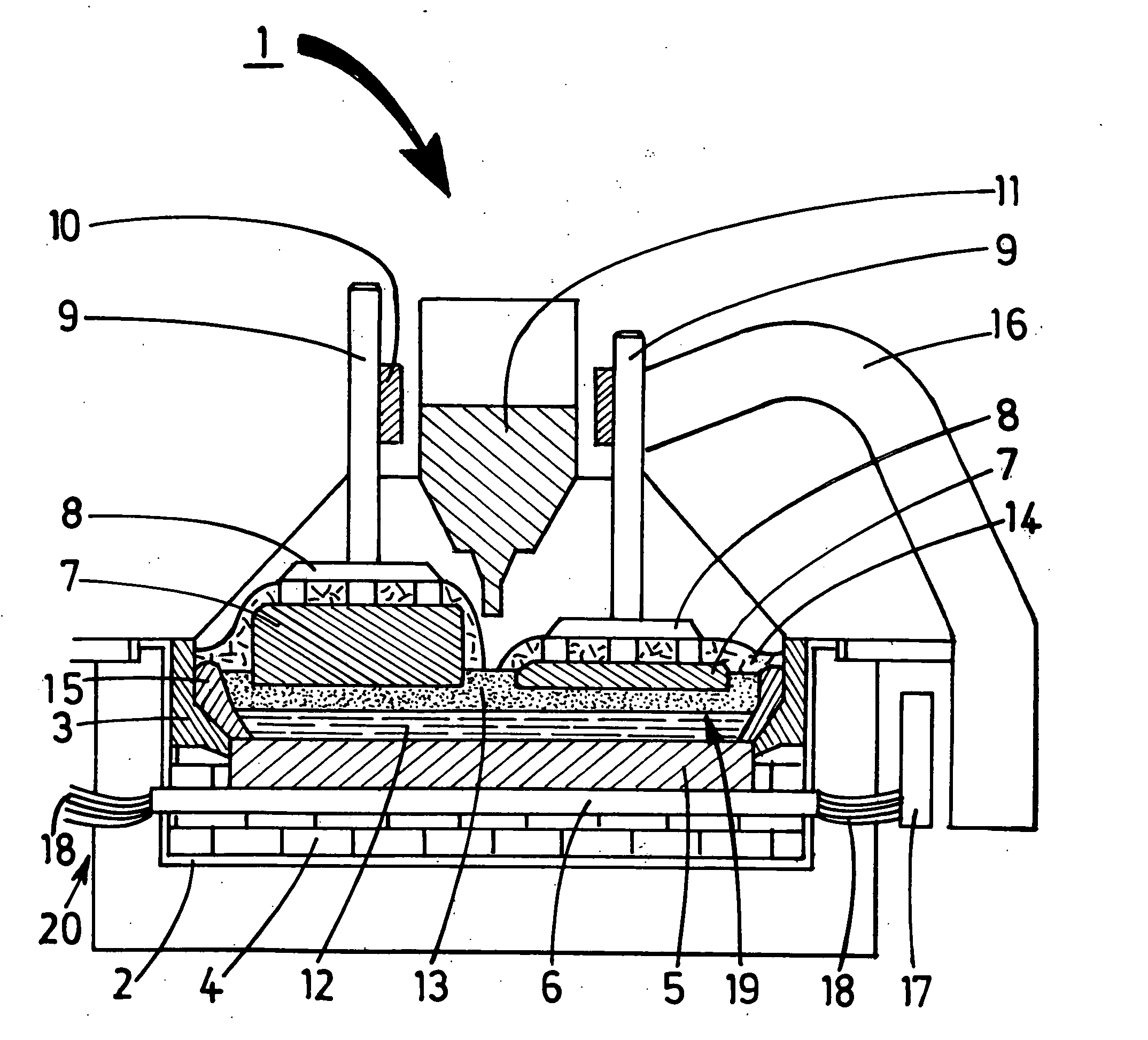
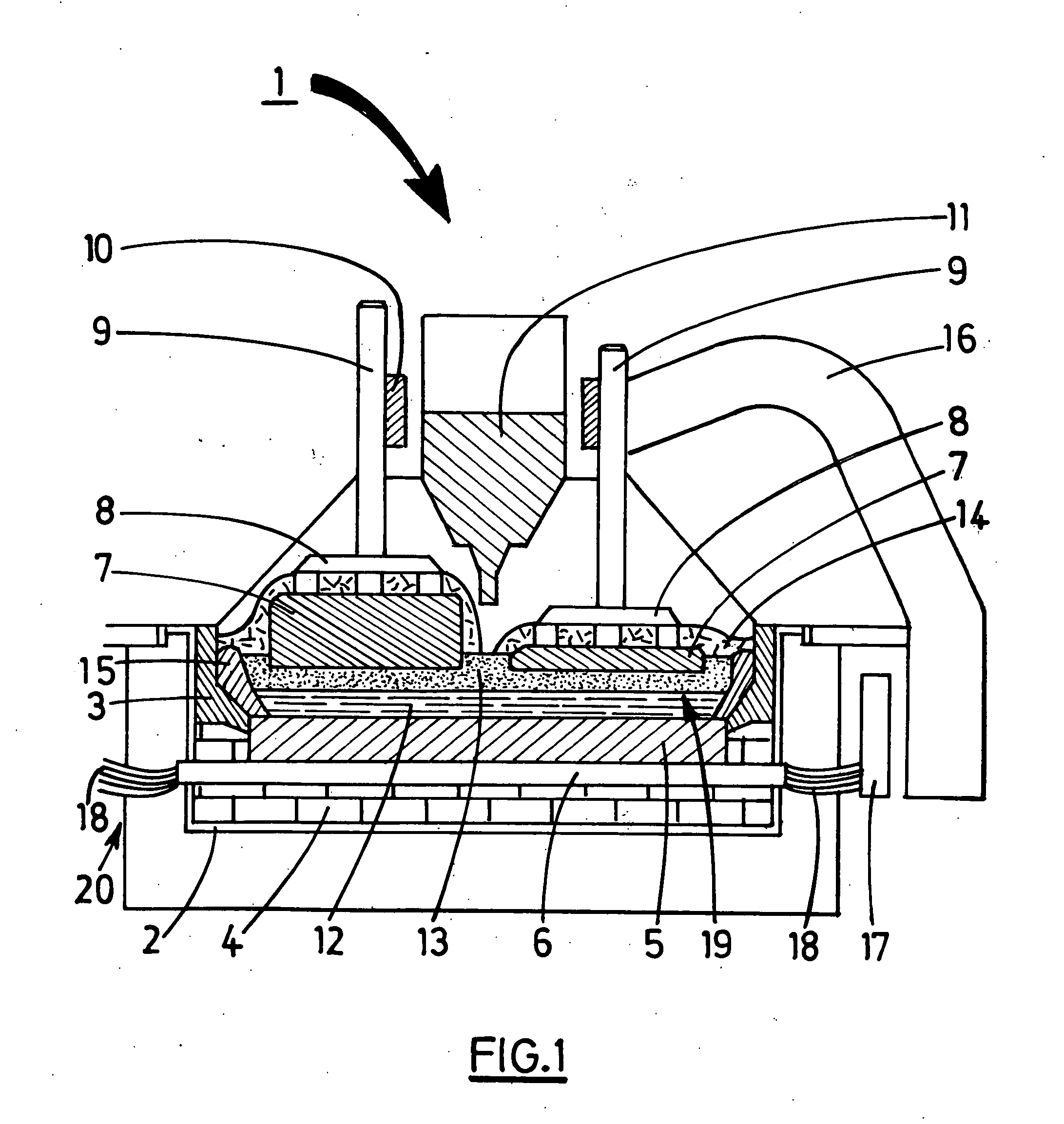
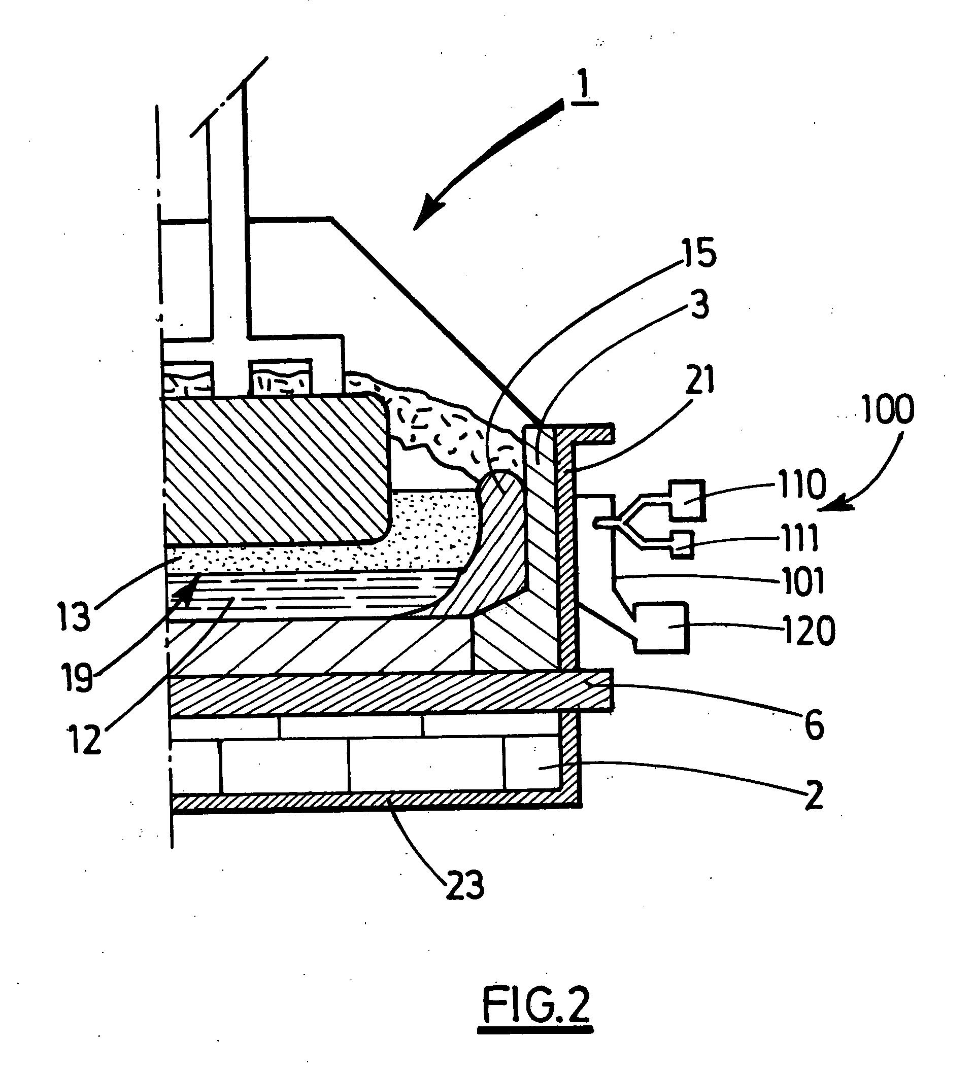
[0011] The invention relates to a method of cooling an igneous electrolytic cell for the production of aluminium wherein a heat transfer fluid (or fluid coolant) absorbs the heat from said cell by a change of phase of all or part of said fluid in contact with the cell pot.
[0012] More specifically, in the method according to the invention, a “divided heat transfer fluid” (or “divided fluid coolant”) is produced, such as droplets of a heat transfer fluid, and all or part of said droplets are placed in contact with the pot shell, so as to induce the vaporisation of all or part of said droplets.
[0013] The heat transfer fluid vapour formed by the vaporisation of all or part of said droplets upon contacting the shell may be evacuated by natural ventilation (such as convection), by blowing or by suction.
[0014] The vaporisation removes heat from the cell and said heat may then be evacuated with the heat transfer fluid vapour. The divided form of the heat transfer fluid makes it possible ...
PUM
| Property | Measurement | Unit |
|---|---|---|
| Size | aaaaa | aaaaa |
| Size | aaaaa | aaaaa |
| Distance | aaaaa | aaaaa |
Abstract
Description
Claims
Application Information