
Orbital welding internal pressure control

a technology of internal pressure control and orbital welding, which is applied in the direction of auxillary welding devices, soldering devices, manufacturing tools, etc., can solve the problems of significant and undesirable head loss in the system, weld bead may not fully envelope the internal diameter weld seam, and the internal diameter of the weld location is reduced, so as to prevent this undesired deposit

Inactive Publication Date: 2006-06-08
ORBITAL ACQUISITION
View PDF3 Cites 9 Cited by
  • Summary
  • Abstract
  • Description
  • Claims
  • Application Information

AI Technical Summary

Benefits of technology

The system ensures consistent, high-quality weld beads with complete penetration, preventing sagging or protrusion, and is compatible with existing orbital welding systems, reducing the risk of rupture and improving manufacturing efficiency.

Problems solved by technology

Often, the result of complete penetration is an undesirable weld bead protrusion into the internal diameter of the tubular component, effectively decreasing this internal diameter at the weld location.
This protrusion can trap impurities during normal operation of the manufactured product and create a significant and undesirable head loss in the system.
For example, the wall thickness of the tube is a significant factor in determining a weld schedule, and require quite dissimilar weld power schedules.
The resulting weld bead may not fully envelope the internal diameter weld seam, if there is even a slight misalignment of the seam versus the electrode of the orbital welder.
This method can result in an unacceptable rate of weld rejection or failure.
Although the concept of supporting the molten weld bead with increased internal pressure is approaching an acceptable solution, there are several major problems with the constant internal flow method.
The first problem occurs if the internal pressure is too low, causing a sagging of the weld bead as previously described.
The second problem occurs when the internal pressure is too high, causing the weld bead to bulge out radially, away from the center of the tubular extensions, characterized by an undesirable increase in internal and external diameters of the tubular extensions at the weld joint.
If the internal pressure is even higher, the gas may cause the molten weld joint between the tubular extensions to rupture, completely destroying the weld bead and, possibly, the components being welded.
A rupture is, for obvious reasons, an extremely undesirable occurrence.
Any one of these problems may occur while using the constant flow positive internal pressure system.
The constant flow positive internal pressure system's inherent unpredictability is caused by the behavior of the tubes during the welding process.
The temporary gap formed at this point allows the internal flow of gas to escape, causing an undesirable internal drop in pressure.
This phenomenon can degrade the quality of the weld or even rupture the weld seam, and potentially destroy the electrode.
Because the internal pressure of the system can change at a rapid rate, it is difficult for a person to accurately manually adjust the flow of internal gas.
This inaccurate and slow method of adjustment can easily result in a flawed weld bead and damage to expensive components.
In addition to the poor quality, low reaction time, and inaccuracies inherent to the manual pressure control system, it is labor intensive, requiring the constant supervision and control by a person.
Essentially, the system may not be compatible with existing orbital welders presently in use, requiring the purchase of both the pressure control system and the compatible orbital welder.

Method used


Image

  • Orbital welding internal pressure control
  • Orbital welding internal pressure control
  • Orbital welding internal pressure control

Examples


Embodiment Construction

[0047] The detailed description set forth below in connection with the appended drawings is intended as a description of presently-preferred embodiments of the invention and is not intended to represent the only forms in which the present invention may be constructed and / or utilized. The description sets forth the functions and the sequence of steps for constructing and operating the invention in connection with the illustrated embodiments. However, it is to be understood that the same or equivalent functions and sequences may be accomplished by different embodiments that are also intended to be encompassed within the spirit and scope of the invention.

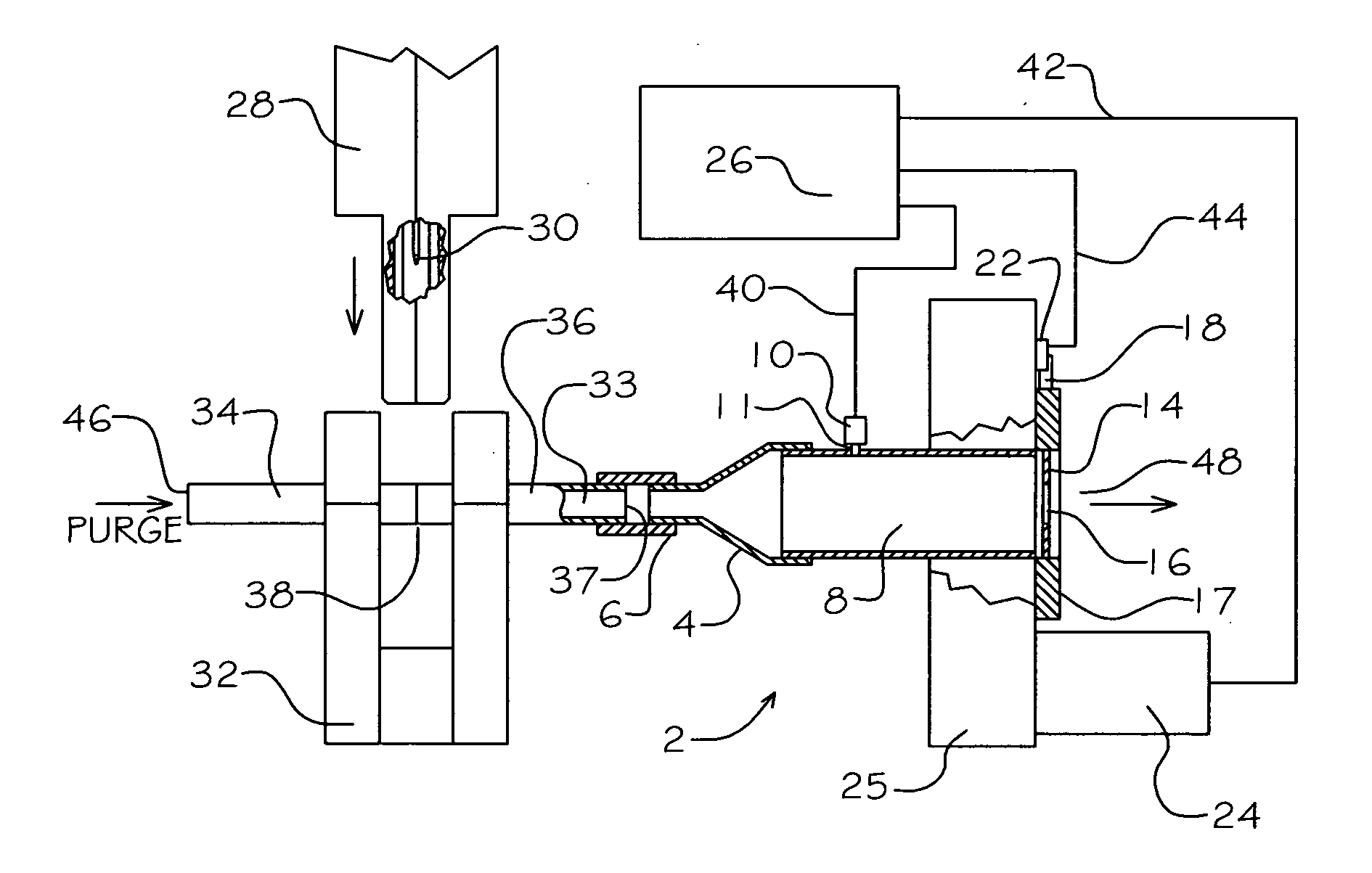
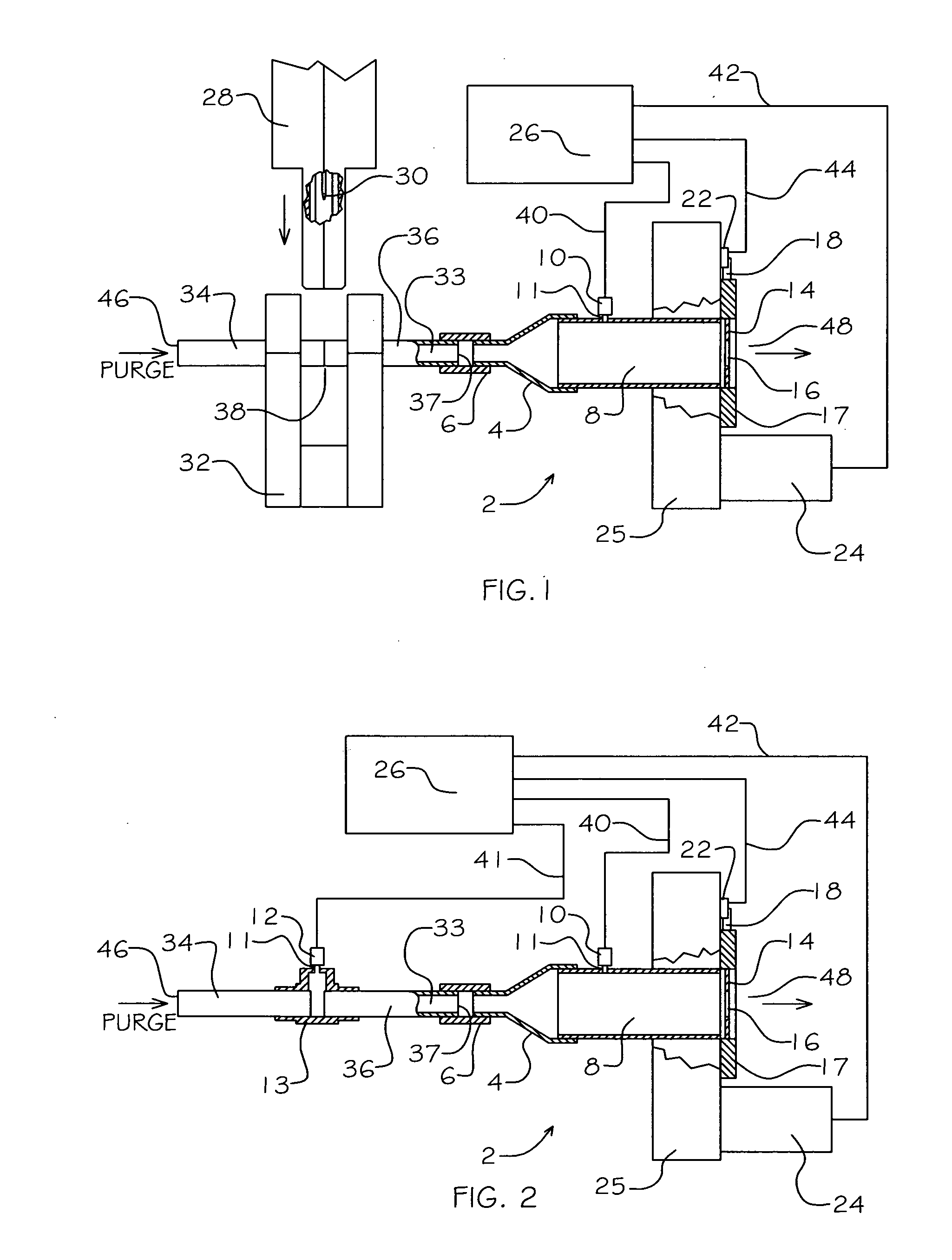
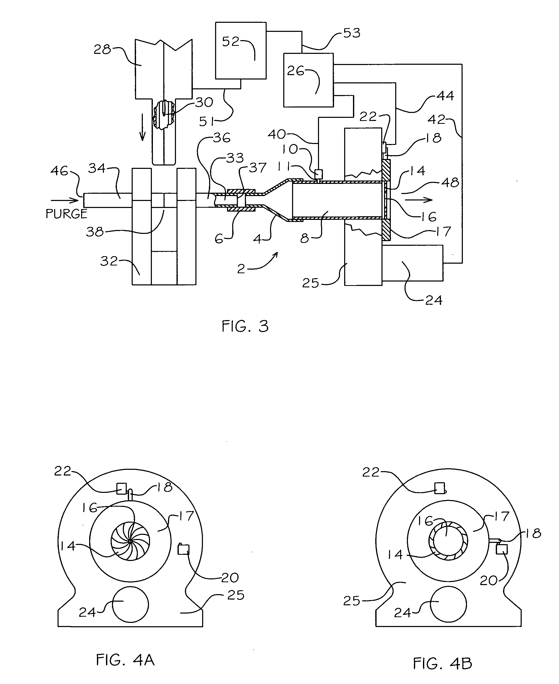
[0048]FIG. 1 illustrates the configuration for welding tubular components utilizing the first mode of operation. When welding together two tubular components (34) and (36) with an orbital welder (28), the components are clamped securely in abutment within a welding fixture (32), with the seam (38) at the juncture of the tubular compon...


PUM

PropertyMeasurementUnit
angleaaaaaaaaaa
diameteraaaaaaaaaa
diameteraaaaaaaaaa

Abstract

A weld bead geometry control system is provided for use in welding in abutment tubes or tubular components. The present invention can accurately and quickly correct for changes in purge gas pressure due to flow losses in real-time, to prevent any undesired protrusion or concavity of a molten weld bead, while allowing complete penetration of the weld. The present invention can additionally dynamically adjust the internal purge pressure to counteract the effects of gravitational pull on the molten weld bead. The weld bead geometry control system can in act in concert with existing orbital welding systems to consistently produce high quality and fully penetrated weld beads that meet or exceed industry standards.

Description

BACKGROUND [0001] 1. Field of Invention [0002] This invention relates generally to a pressure sensing and control device, and, more particularly, to a device enabling the adjustment of purge gas flow automatically and dynamically during the orbital welding of tubular components, to maintain a desired internal tube pressure, for the purpose of affecting the internal geometry of a molten weld bead and reducing particle generation. Additionally, the present invention relates to a device enabling the adjustment of purge gas flow and pressure relative to the activity of an orbital tube welder, again for the purpose of affecting the internal geometry of a molten weld bead and reducing particle generation during the weld. [0003] 2. Description of Prior Art [0004] When welding in abutment two metal tubes or components with tubular extensions, using an orbital welding device, such as the device disclosed in U.S. Pat. No. 5,196,664 to McGushion (1993), it is generally a desired result to crea...

Claims


Application Information

Patent Timeline
Patent Type & Authority Applications(United States)
IPC IPC(8): B23K9/16
CPCB23K9/0286B23K9/095B23K9/325
Inventor MCGUSHION, KEVIN DAVID
Owner ORBITAL ACQUISITION
Learn More