Image forming apparatus and its control method

a technology of image forming apparatus and control method, which is applied in the field of color image technology, can solve the problems of difficult to obtain high-quality full-color images, take a long time to complete image formation, and remain unsolved, and achieve the effect of suppressing the generation of moiré

Inactive Publication Date: 2006-06-08
CANON KK
View PDF9 Cites 35 Cited by
  • Summary
  • Abstract
  • Description
  • Claims
  • Application Information

AI Technical Summary

Benefits of technology

[0014] The present invention has been made to solve the aforementioned problems, and has as its object to provide a technique for forming a high-quality image by correcting any color shifting first by calculating the read coordinate position of image data to be printed on the basis of shifting amount information indicating a shifting amount with respect to the scanning direction on an image carrier of each image forming unit, and then executing halftone processing to print an image, thus suppressing generation of moiré due to color shifting correction.

Problems solved by technology

With this method, the image forming process must be repeated three or four times (using black) per print image, and takes a long time to complete image formation.
However, color shifting owing to position shifts of respective colors on a transfer sheet occurs due to the positional precision and diameter shifts of the respective photosensitive bodies, positional precision shifts of optical systems, and the like, and it becomes difficult to obtain a high-quality full-color image.
However, with the technique of reference 1, the following problems remain unsolved.
That is, high-precision movable members are required, resulting in high cost.
Furthermore, since it takes a long time until completion of correction, the correction cannot be frequently made.
Also, the optical path lengths often change as an elapse of time due to temperature rise of a machine.
In such case, it is difficult to prevent any color shifting by correcting the optical paths of the optical systems.
However, any tilt of an optical system or any magnification shifting due to some optical path length shifting cannot be corrected.
Therefore, when such nonuniform density values appear periodically, moiré becomes obvious, and a high-quality color image cannot be obtained.
However, when a given image forming unit scans in a direction opposite to that of another image forming unit, a cause of color nonuniformity is generated.
Since the scan speed and rotational speed of the drum vary depending on a print mode, color shifting cannot be suppressed by single processing so far.

Method used


Image

  • Image forming apparatus and its control method
  • Image forming apparatus and its control method
  • Image forming apparatus and its control method

Examples


first embodiment

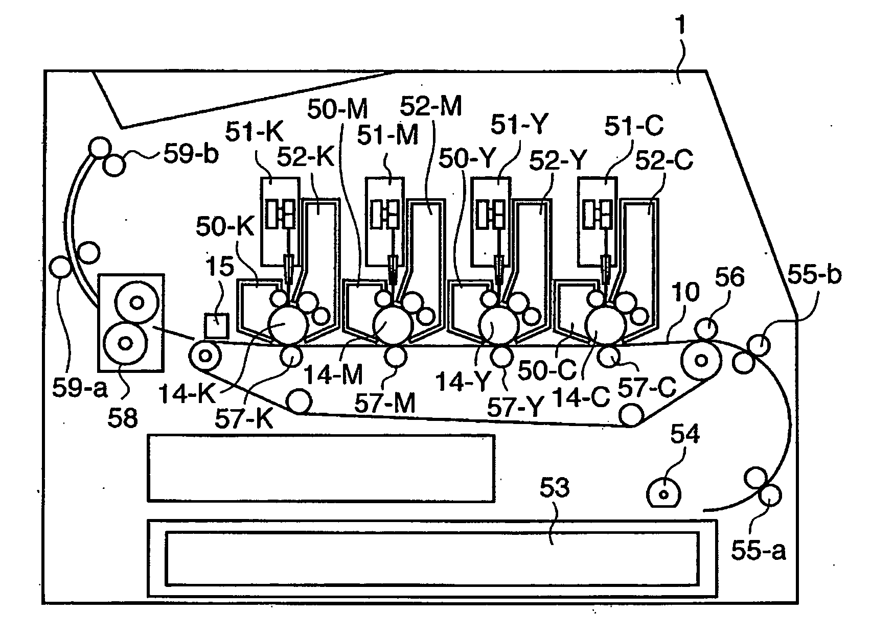
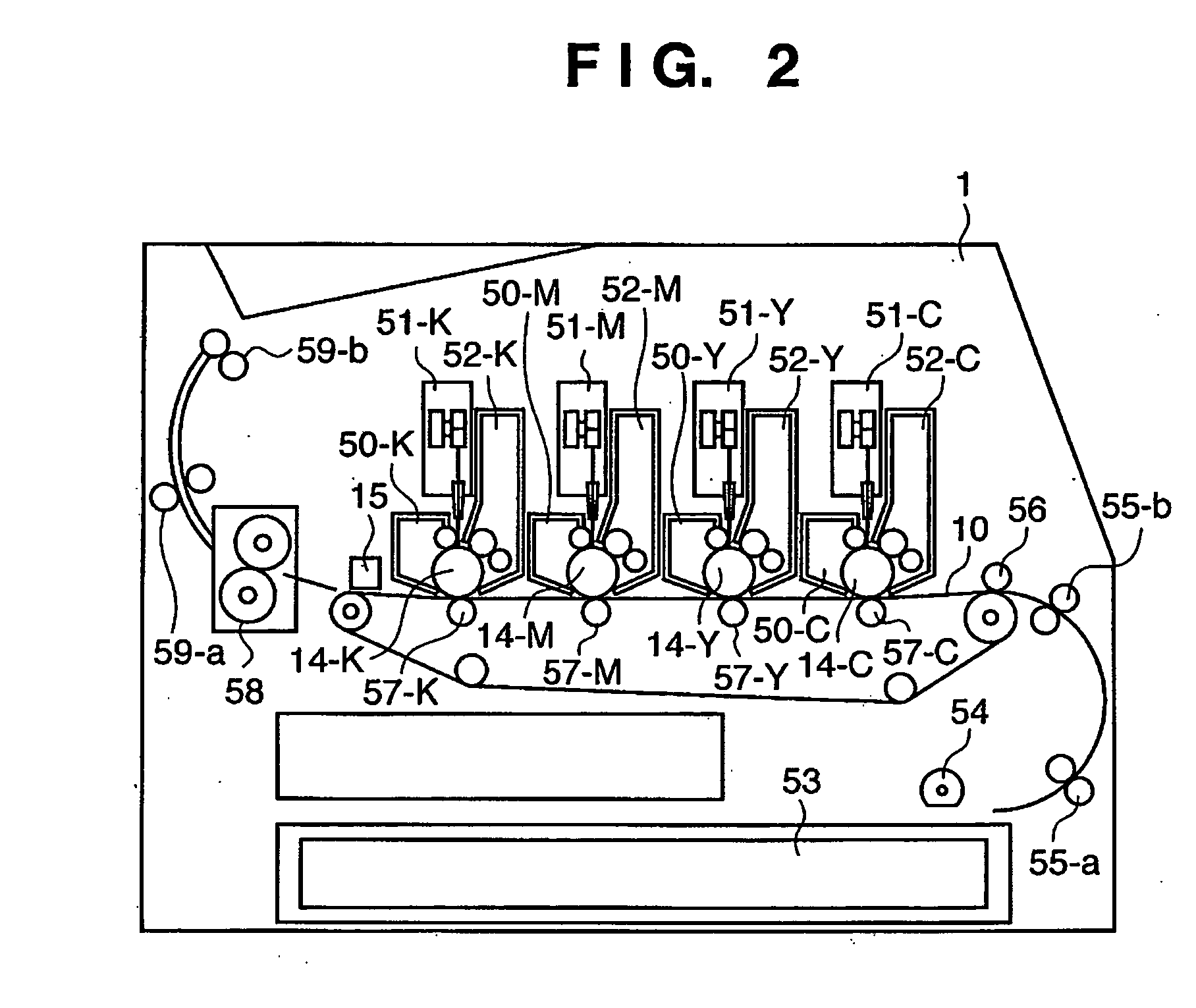
[0073]FIG. 2 is a sectional view showing the structure of an image forming apparatus according to this embodiment.

[0074] As shown in FIG. 2, the image forming apparatus of this embodiment has a structure of a 4-drum color laser beam printer.

[0075] This image forming apparatus mounts a transfer sheet cassette 53 in a lower portion on the right side of FIG. 2. Print media (print sheets, transparent sheets, or the like) set in the transfer sheet cassette 53 are picked up one by one by a paper feed roller 54 and are fed to image forming units by a pair of conveying rollers 55-a and 55-b. The image forming units are provided with a transfer conveyor belt 10 for conveying a print medium. The transfer conveyor belt 10 is tightened flat by a plurality of rollers in the print medium conveying direction (from the right to left in FIG. 2), and a print medium is electrostatically attracted on the conveyor belt 10 at its most upstream portion. Four photosensitive drums 14-C, 14-Y, 14-M, and 14...

second embodiment

[0140] The second embodiment will be described below.

[0141]FIG. 12 is a block diagram for explaining the operation of the color shifting correction processing for correcting any color shifting generated due to the slope and curvature of the scan line in the second embodiment. The difference between FIG. 4 in the first embodiment and FIG. 12 is that the color shifting correction units 408C, 408M, 408Y, and 408K are replaced by units 408C′, 408M′, 408Y′, and 408K′. Also, in addition to the color shifting correction units 408C, 408M, 408Y, and 408K, exception processors 411C, 411M, 411Y, and 411K are added, and selectors 412C, 412M, 412Y, and 412K each for selecting one of outputs of the halftone processors 409C, 409M, 409Y, and 409K and those of the exception processors 411C, 411M, 411Y, and 411K are added.

[0142] Other arrangements are the same as those of the first embodiment, and differences will be explained below.

[0143] The color shifting correction units 408C′, 408M′, 408Y′, a...

third embodiment

[0175] The third embodiment will be described below.

[0176]FIG. 16 is a block diagram for explaining the operation of the color shifting correction processing for correcting any color shifting generated due to the slope and curvature of the scan line in the third embodiment. The difference between FIG. 12 in the second embodiment and FIG. 16 is that the engine 401 comprises exposure profile storage units 1403C, 1403M, 1403Y, and 1403K, and a print profile storage unit 1420. Based on this, color shifting correction amount arithmetic units 1407C, 1407M, 1407Y, and 1407K are arranged.

[0177] The exposure profile storage units 1403C, 1403M, 1403Y, and 1403K store the same data as in the color shifting amount storage units 403C, 403M, 403Y, and 403K in the first and second embodiments. That is, the exposure profile storage units 1403C, 1403M, 1403Y, and 1403K receive and hold the shifting amount information for respective image forming units of respective colors in the manufacturing proc...


PUM


Abstract

With this invention, color shifting correction is performed first based on shifting amount information indicating a shifting amount with respect to the scanning direction on an image carrier of each image forming unit, and halftone processing is then performed, thus suppressing generation of moiré due to the color shifting correction, and forming a high-quality image. To this end, an image forming engine has color shifting amount storage units C, M, Y, and K (black) which store actual shifting amounts with respect to ideal scan directions on image carriers C, M, Y, and K in image forming units C, M, Y, and K. Color shifting correction amount arithmetic units C, M, Y, and K calculate color shifting correction amounts for respective color components on the basis of the stored color shifting amounts. Color shifting correction units C, M, Y, and K perform color shifting correction by converting coordinates upon reading out image data from bitmap memories C, M, Y, and K on the basis of the calculated color shifting correction amounts, and then perform tone correction. Data after tone correction undergo halftone processing by halftone processors C, M, Y, and K. PWM processors C, M, Y, and K generate PWM signals for scanning, and output them to exposure units C, M, Y, and K of the respective image forming units.

Description

FIELD OF THE INVENTION [0001] The present invention relates to a technique for forming a color image by transferring color formers that form color component images to be developed on a plurality of juxtaposed image carriers onto a conveyed print medium. BACKGROUND OF THE INVENTION [0002] Conventionally, as a color image forming apparatus which uses an electrophotography method, an apparatus which uses a plurality of developers for one photosensitive body to develop respective color components is known. This apparatus repeats an “exposure-development-transfer” process as many as the number of color components to overlay and form color images on a single transfer sheet in these processes, and to fix these color images, thus obtaining a full-color image. [0003] With this method, the image forming process must be repeated three or four times (using black) per print image, and takes a long time to complete image formation. [0004] As a method that can cover this shortcoming, a technique t...

Claims


Application Information

Patent Timeline
Patent Type & Authority Applications(United States)
IPC IPC(8): H04N1/409
CPCH04N1/506H04N1/60G03G15/5008H04N1/58H04N1/29G06F3/12G06K15/14G06K15/1878G06K15/188G06K15/1881H04N1/40062H04N1/4092H04N1/52H04N1/6027H04N1/6072
Inventor TAKATA, TSUTOMUKITAMURA, HIROKIAKIBA, YOSHIYUKINAKAMURA, SHUICHIYAMAMOTO, YUSUKEMOTOYAMA, MASANAOAKIYAMA, TAKESHITOJIMA, KENZONAGAOKA, TAKAAKI
Owner CANON KK
Why Eureka
Try Eureka