Optical system providing several beams from a single source

a technology of optical system and beam, applied in the field of optical system, can solve the problems of device construction that is somewhat complicated and may require careful calibration and correction, and achieve the effect of simple construction, easy manufacturing, and no need for complicated calibration or adjustmen

Active Publication Date: 2006-06-08
SPECTRA PRECISION (USA) LLC
View PDF20 Cites 7 Cited by
  • Summary
  • Abstract
  • Description
  • Claims
  • Application Information

AI Technical Summary

Benefits of technology

[0017] Accordingly, it is a feature of embodiments of the present invention to have a device comprising a single laser source and a simple optic that accurately produces several orthogonal beams, originating from a common point. The optic is simple in construction, easily manufactured and does not require complicated calibration or adjustment. Because the design of the optic is simple, the cost of the optic components is minimized.

Problems solved by technology

However, these devices are somewhat complicated in construction, and therefore expensive to make.
Because of this complexity, such devices may require careful calibration and correction.

Method used


Image

  • Optical system providing several beams from a single source
  • Optical system providing several beams from a single source
  • Optical system providing several beams from a single source

Examples


Embodiment Construction

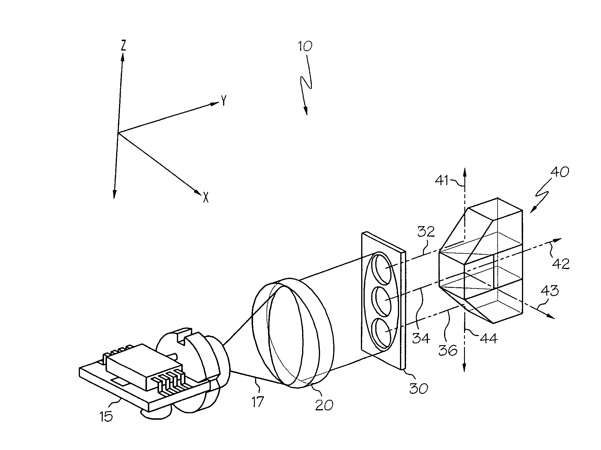
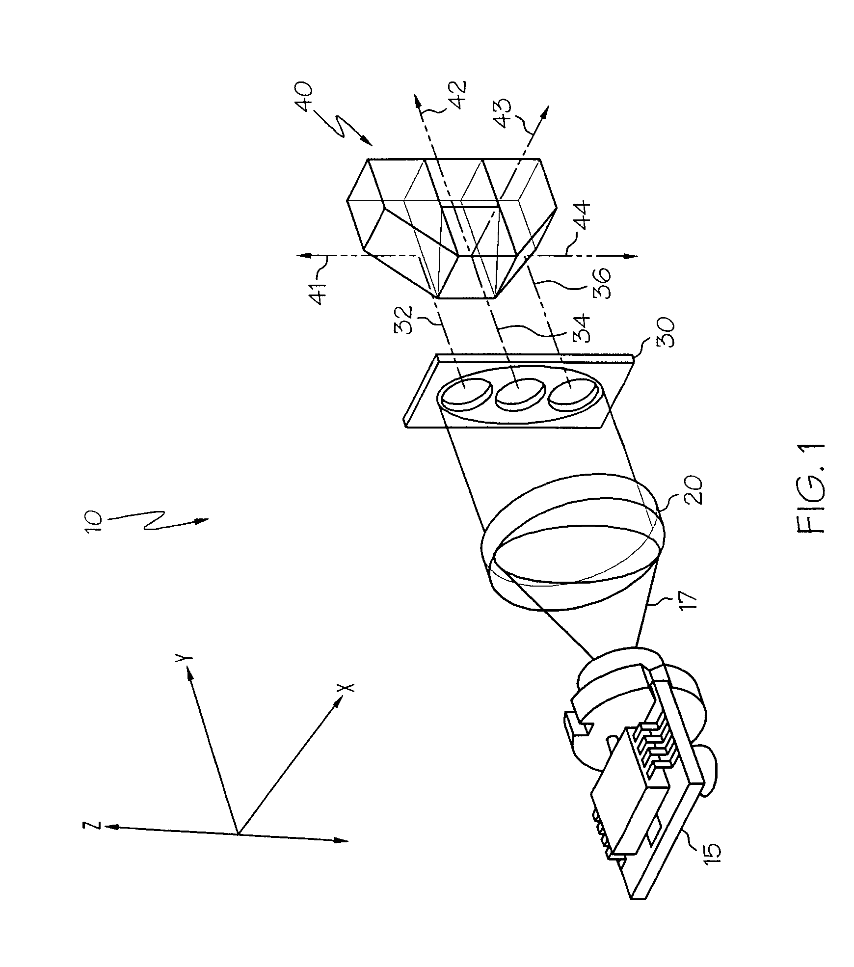
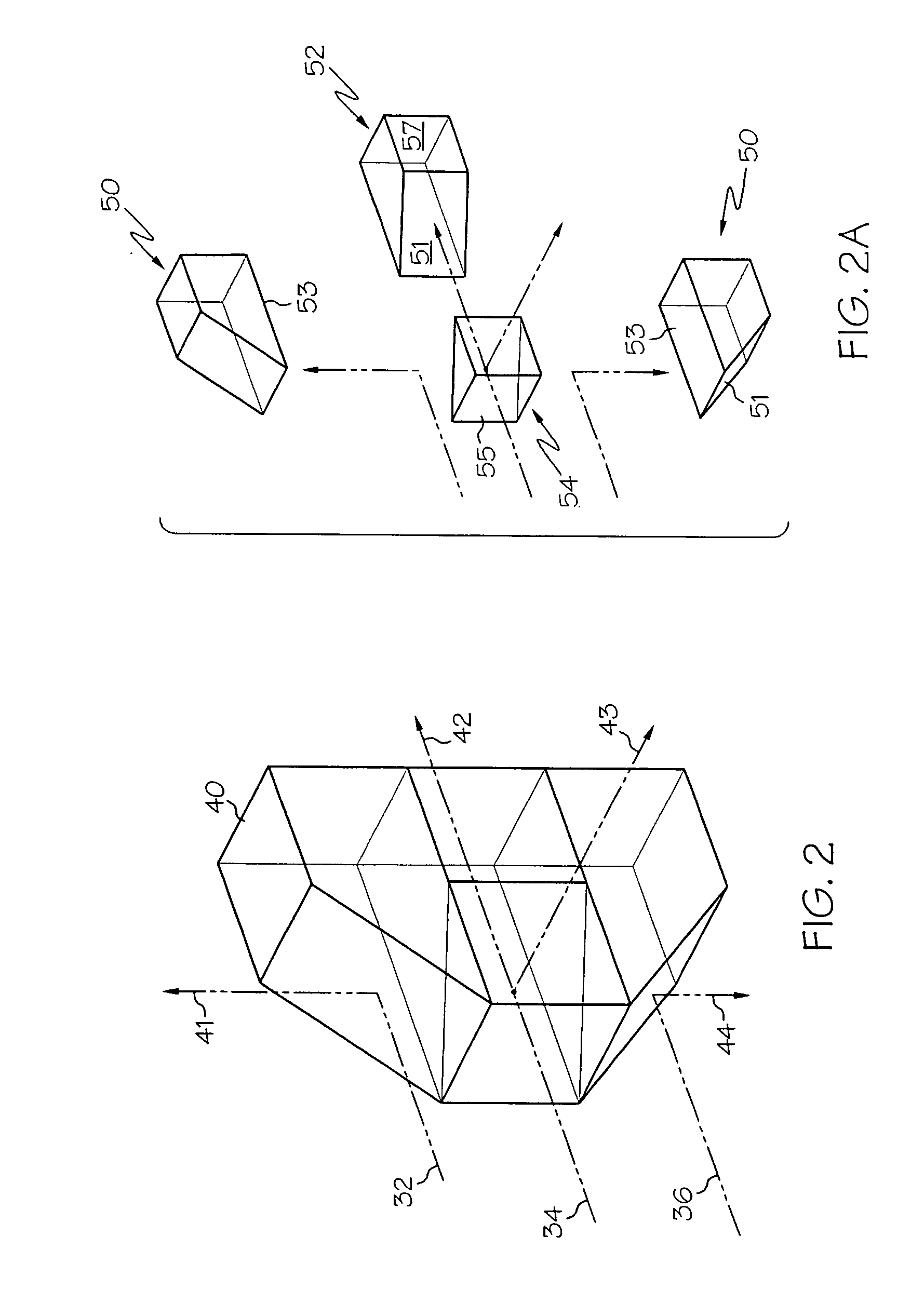
[0038]FIG. 1 illustrates a system 10 comprising a single light source 15 generating a beam of light 17 that shines on an optic 40. The optic 40, in turn, produces four orthogonal beams 41, 42, 43, 44 which are oriented and aligned so as to appear to be originating from a single coincident point within the optic 40. The light source 15 is preferably a laser diode which generates a beam of light 17 which is generally elliptical in cross-section. The beam of light 17 is projected generally along the y-axis. The elliptical beam of laser light 17 passes through a collimating lens 20 and in conjunction with an aperture 30 produces three parallel, collimated beams of laser light 32, 34, and 36. Beam 34, the “Level” beam, has approximately half the power of the sum of the apertured beams 17. Beams 32 and 36, the “Plumb” beams, each have approximately a quarter of the power of the sum of the apertured beams 17. The three beams 32, 34 and 36 are projected onto the optic 40. The optic 40 both ...


PUM


Abstract

A system to produce orthogonal beams includes a laser diode operating in conjunction with a collimating lens, with or without an aperture, and a simple compact optic. At least one collimated beam is directed toward an optic comprised of components that are bonded together. Beams are reflected from at least one optical components at right angles to produce a plumb beam. Additionally, a beam is reflected from the optic at a right angle, as well as transmitted through the optic, to produce square and level beams. All beams are orthogonal to each other, have relatively equal power, and are aligned and oriented so as to appear to be originating from a coincident point. An optional orthogonal beam may be produced. An optic in the shape of a cuboid comprised of six small components is also disclosed.

Description

CROSS REFERENCE TO RELATED APPLICATIONS [0001] This application is a continuation-in-part of U.S. patent application Ser. No. 10 / 818,423 filed Apr. 5, 2004, now allowed.BACKGROUND OF THE INVENTION [0002] The present invention generally relates to an optical system that may have utility in construction lay-out and, more specifically, to a system including a simple optic producing at least three orthogonal beams from an incoming collimated laser beam. [0003] In the construction and home improvement industries, it is quite common for workers to determine level and square along a wall or potential wall site, as well as to find a plumb line from floor to ceiling, during the process of laying out a room. It is advantageous to make these measurements with one device at one time, and at a coincidental point. If the measurements are taken simultaneously with a single device from a coincidental point, the accuracy of the measurements taken increases. By not moving a measurement device from po...

Claims


Application Information

Patent Timeline
Patent Type & Authority Applications(United States)
IPC IPC(8): G02B27/12G01C15/00G02B5/04G02B27/14
CPCG02B5/04G02B27/144G02B19/0014G01C15/12G02B19/0057G01C15/10
Inventor MORRISSEY, KEVIN MARCSCHAEFER, JASON ALAN
Owner SPECTRA PRECISION (USA) LLC
Why Eureka
Try Eureka