Sintering resistant, low conductivity, high stability thermal barrier coating/environmental barrier coating/environmental barrier coating system for a ceramic-matrix composite (CMC) article to improve high temperature capability

Active Publication Date: 2006-06-08
GENERAL ELECTRIC CO
View PDF42 Cites 34 Cited by
  • Summary
  • Abstract
  • Description
  • Claims
  • Application Information

AI Technical Summary

Benefits of technology

[0012] Accordingly, there is a need in the art for an improved TBC for use in an TBC/EBC system which provides sufficient thermal and environmental protection to underlying silicon based substrate components operating at temperatures of about 3000° F. (

Problems solved by technology

However, as operating temperatures increase, the high temperature durability of the components of the engine must correspondingly increase.
However, it has been found that silicon containing substrates can recede and lose mass as a result of a formation volatile Si species, particularly Si(OH)x and SiO when exposed to high temperature, aqueous environments.
), these systems may encounter problems when the EBC and the component are subjected to higher operating temperatures above 2500° F. In particular, for application temperatures approaching the melting temperature of BSAS (about 1700° C.
Further still, as application temperatures increase further beyond the thermal capability of a Si-containing material (limited by a melting temperature of about 2560° F.
(about 1404° C. ) for silicon), conventional TBC's mentioned above may not adequately protect the underlying component.
However, as coating thickness increases, strain energy due to the CTE mismatch between individual coating layers and the substrate increases as well, which

Method used


Image

  • Sintering resistant, low conductivity, high stability thermal barrier coating/environmental barrier coating/environmental barrier coating system for a ceramic-matrix composite (CMC) article to improve high temperature capability
  • Sintering resistant, low conductivity, high stability thermal barrier coating/environmental barrier coating/environmental barrier coating system for a ceramic-matrix composite (CMC) article to improve high temperature capability
  • Sintering resistant, low conductivity, high stability thermal barrier coating/environmental barrier coating/environmental barrier coating system for a ceramic-matrix composite (CMC) article to improve high temperature capability

Examples


Embodiment Construction

[0022] Embodiments of the invention improve upon prior systems TBC / EBC systems used on substrates and / or components comprised of silicon containing materials for high temperature applications. It does so by providing a thermal barrier coating which exhibits better resistance to sintering, improved phase stability, lower thermal conductivity, thereby allowing the silicon material containing substrate to operate at higher temperatures and also for longer durations than some conventional TBC / EBC systems which utilize conventional thermal barrier coatings such as 7% YSZ. Some examples of TBC / EBC systems of embodiments of the present invention are discussed below.

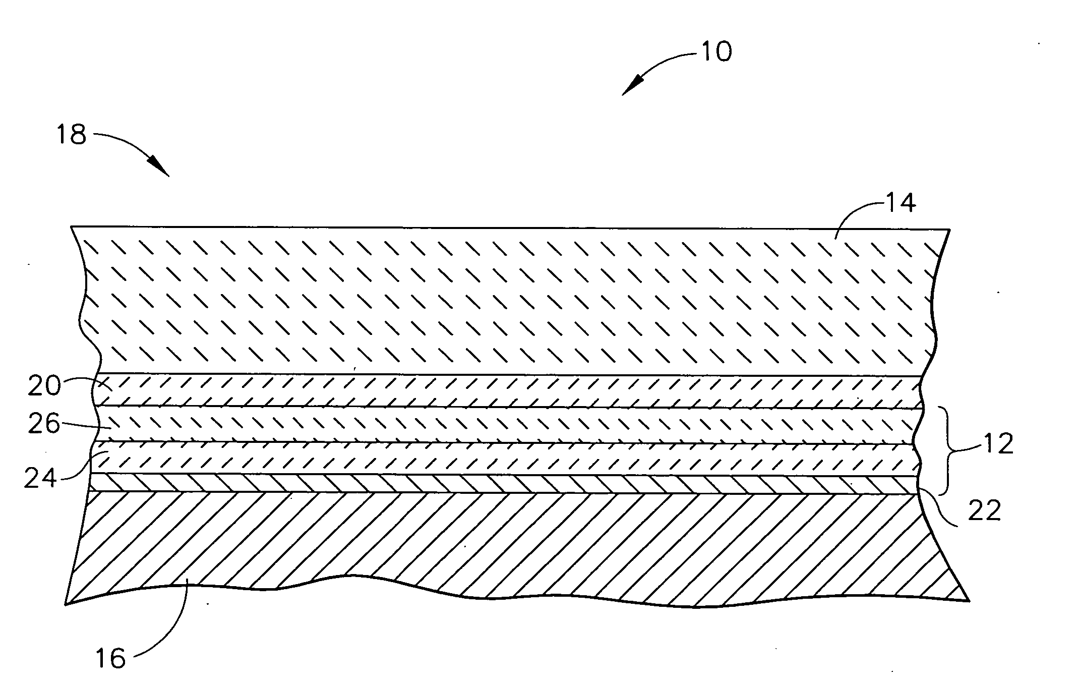
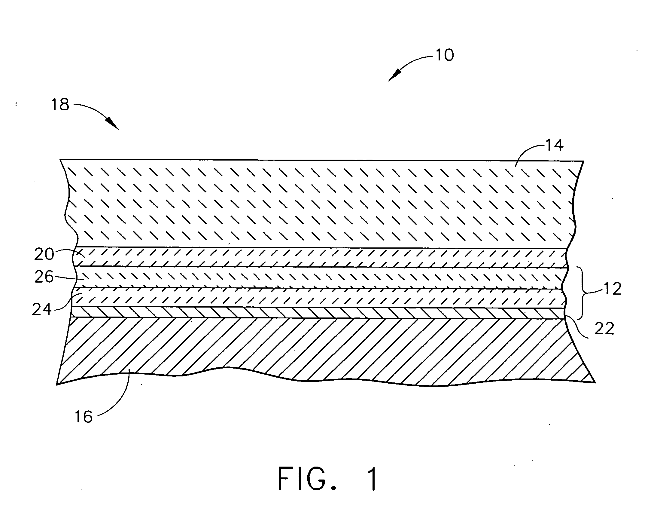
[0023] Referring to FIG. 1, a TBC / EBC system 10 of a first embodiment of the present invention is shown. The TBC / EBC system 10 includes an EBC 12, a TBC 14 or top coat and a surface region 16 or substrate of a hot section component 18. The TBC / EBC system of the first embodiment further optionally comprises a CTE transition laye...


PUM

PropertyMeasurementUnit
Percent by massaaaaaaaaaa
Temperatureaaaaaaaaaa
Electrical conductivityaaaaaaaaaa

Abstract

In accordance with an embodiment of the invention, a thermal barrier coating (TBC) for inclusion in a thermal barrier coating/environmental barrier coating system (TBC/EBC system) for use on a silicon containing material substrate is provided. The TBC comprises a compound having a primary constituent portion and a stabilizer portion stabilizing said primary constituent. The primary constituent portion of the TBC comprises hafnia present in an amount of at least about 5 mol % of the primary constituent. The stabilizer portion of said thermal barrier coating comprises at least one metal oxide comprised of cations with a +2 or +3 valence present in the amount of about 10 to about 40 mol % of the thermal barrier coating.

Description

CROSS-REFERENCE TO RELATED APPLICATION [0001] The subject application shares certain attributes with U.S. Ser. No. ______, entitled, “Low Thermal Conductivity Thermal Barrier Coating System and Method Therefor” and with U.S. Ser. No. ______, entitled, “Thermal Barrier Coating / Environmental Barrier Coating System For A Ceramic-Matrix Composite (CMC) Article To Improve High Temperature Capability”, each of which are filed concurrently herewith.GOVERNMENT RIGHTS [0002] The invention was made in part under contract number N00421-00-3-0536 awarded by the Government (Navy). Accordingly, the Government has certain rights in this invention.FIELD OF THE INVENTION [0003] This invention relates to coating systems suitable for protecting components exposed to high-temperature environments, such as the hostile thermal environment of a gas turbine engine. More particularly, this invention is directed to a thermal / environmental barrier coating system for a substrate formed of a material containing...

Claims


Application Information

Patent Timeline
IPC IPC(8): B32B15/04B32B9/00
CPCC04B41/009C04B41/52C04B41/89F01D5/288C04B41/4527C04B41/5096C04B41/5024C04B41/5037C04B41/5042C04B41/5031C04B41/522C04B41/4529C04B35/565C04B35/584C04B35/806C04B35/597F05D2230/90F05D2300/611F05D2300/2118F05D2300/50211C23C28/042
Inventor BOUTWELL, BRETT ALLEN ROHRERSPITSBERG, IRENEGOVERN, CHRISTINENAGARAJ, BANGALORE A.HAZEL, BRIAN THOMAS
Owner GENERAL ELECTRIC CO
Why Eureka
Try Eureka