Apparatus to automatically lyse a sample

a technology of automatic lysing and sample, which is applied in the direction of instruments, grain treatment, analysis using chemical indicators, etc., can solve the problems of potentially destructive temperature changes in particular samples, and achieve the effect of maintaining the heat removal rate and minimizing the risk of cross contamination

Inactive Publication Date: 2006-06-08
MICROFLUIDIC SYST
View PDF46 Cites 16 Cited by
  • Summary
  • Abstract
  • Description
  • Claims
  • Application Information

AI Technical Summary

Benefits of technology

[0010] The lysing system of the present invention preferably utilizes a disposable, individually capped sample vial for each sample to be lysed, minimizing the risk of cross contamination between tests. The sample can be combined with mechanical agitation media (e.g. glass spheres), chemical lysing reagents (e.g. NaOH), other conventional lysing techniques, or nothing depending on the lysing protocol. A sample vial holding the sample is inserted into the lysing device such that the bottom of the sample vial comes in contact with the transducer tip of the ultrasonic transducer. The transducer tip does not come in contact with the sample. The sample vial is inserted into a vial mount within the lysing device. Heat blocks are pressed tightly against the side walls of the sample vial. The heat blocks are each mounted to a Thermoelectric Cooler (TEC) and heatsink. The ultrasonic transducer transmits ultrasonic energy through the bottom of the sample vial and into the sample to cause cell / spore / tissue disruption. When the cooling function is activated, the TECs actively cool the sample by pulling heat from the sample vial via the heat blocks. Preferably an auxiliary fan blows across the TECs and heatsinks to maintain the heat removal rate.

Problems solved by technology

During certain lysing protocols, temperatures can increase to a point that are potentially destructive to particular samples.

Method used


Image

  • Apparatus to automatically lyse a sample
  • Apparatus to automatically lyse a sample
  • Apparatus to automatically lyse a sample

Examples


Embodiment Construction

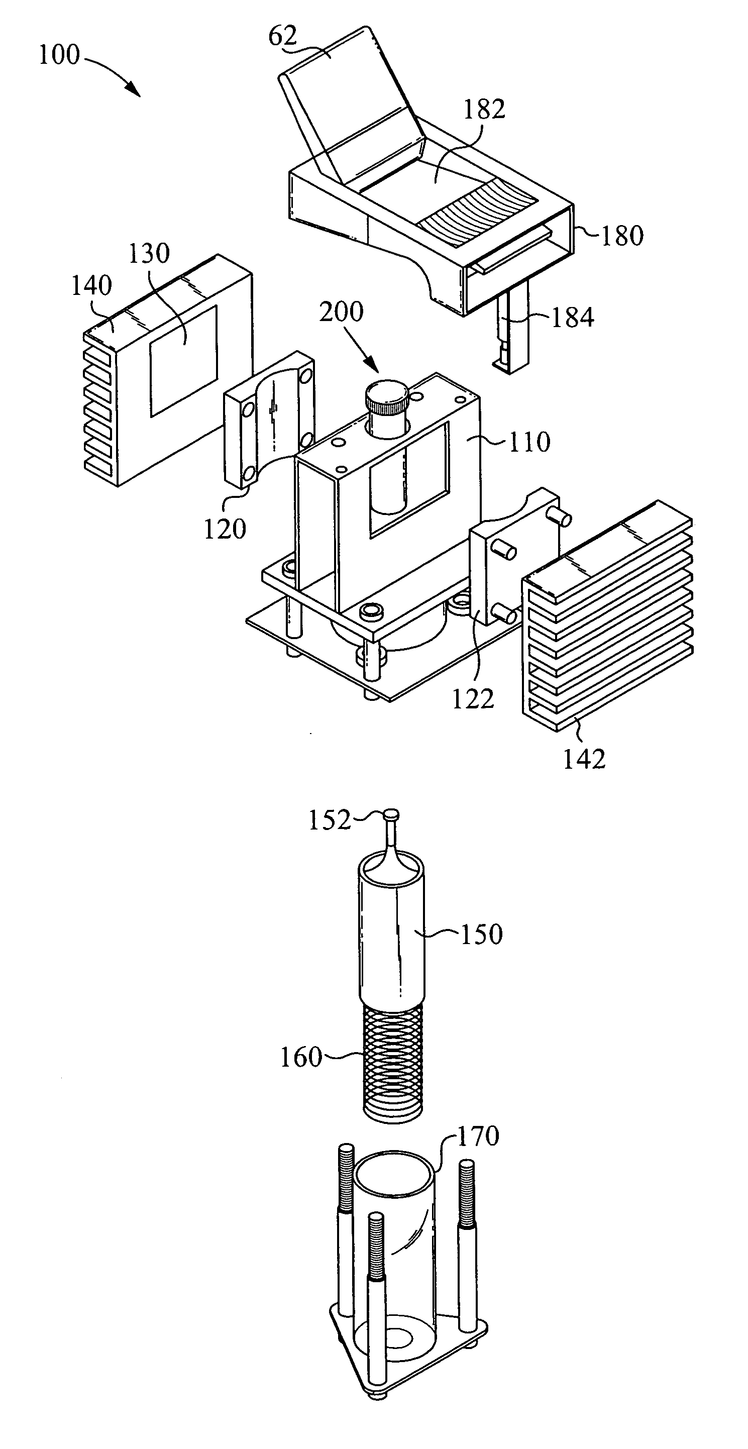
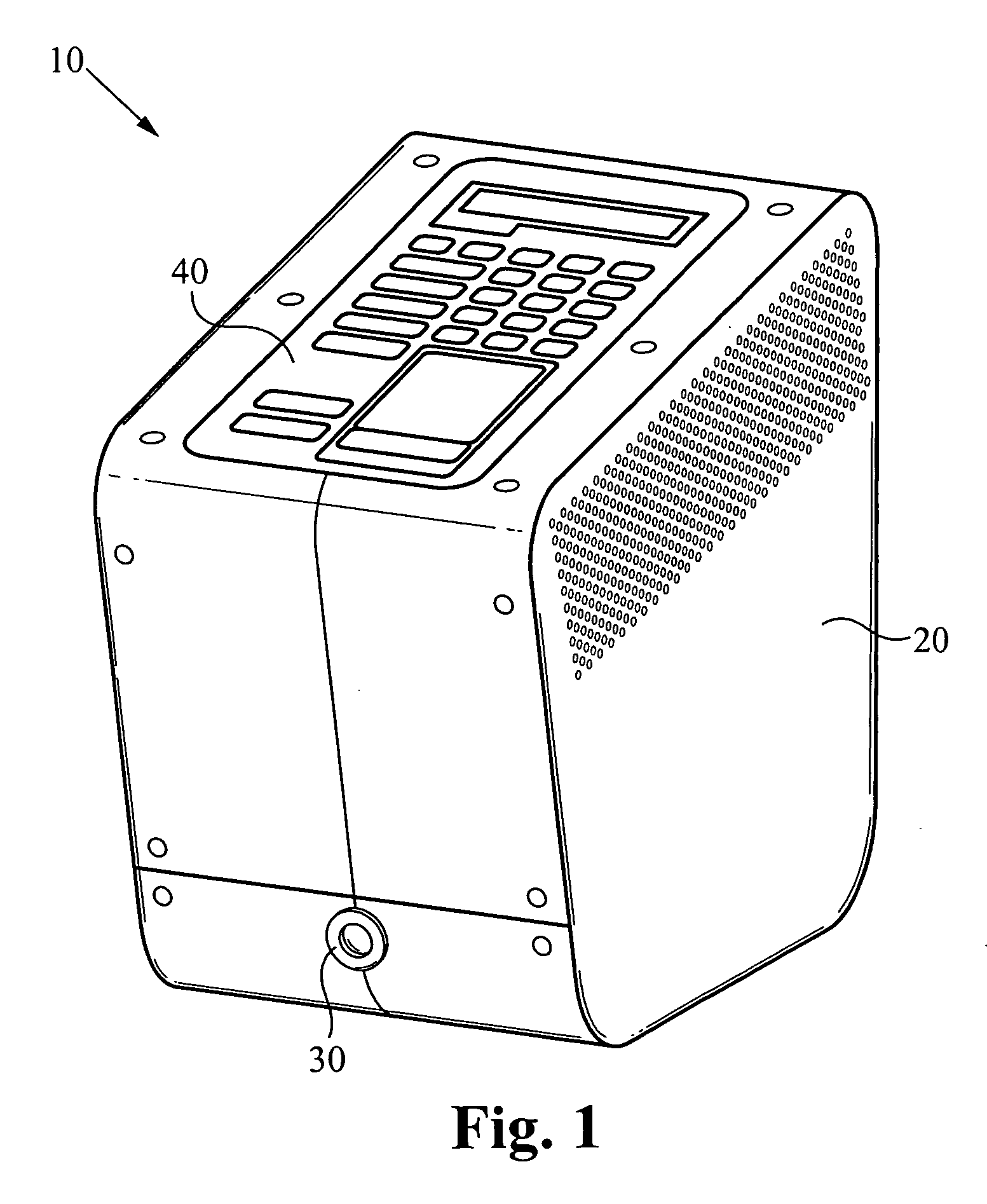
[0016]FIG. 1 illustrates a perspective view of an automatic lysing device 10 according to a preferred embodiment of the present invention. The lysing device 10 includes a housing 20, a main power switch 30, and a control panel 40.

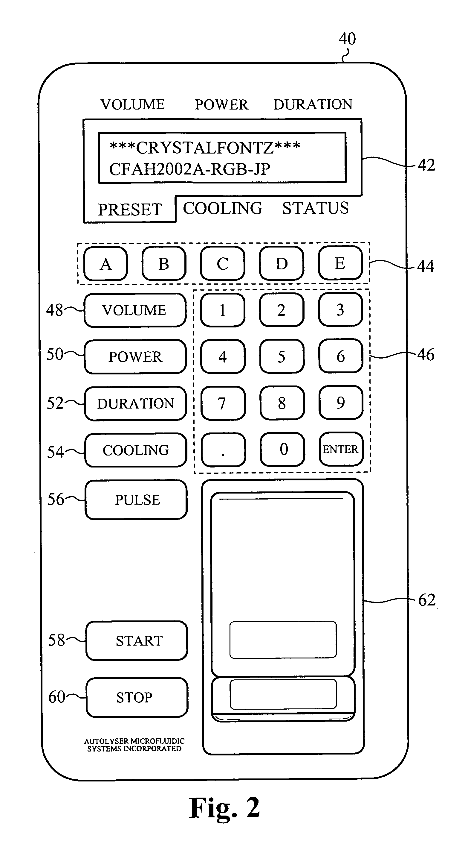
[0017]FIG. 2 illustrates the control panel 40 in greater detail. The control panel 40 is a user interface that enables a user to input various lysing protocol parameters. A visual display 42 displays the input parameters as well as feedback and status information during operation. The display 42 is preferably a liquid crystal display (LCD). Alternatively, any conventional display device is used. Less desirably, a printer such as a paper tape printer, can be used. A volume button 48, a power button 50, a duration button 52, and a cooling button 54 enable the user to enter a volume parameter, a power parameter, a duration parameter, and a cooling parameter, respectively. A numeric keypad 46 enables the user to enter numeric values associated with the volume,...


PUM

PropertyMeasurementUnit
volumesaaaaaaaaaa
volumesaaaaaaaaaa
volumesaaaaaaaaaa

Abstract

A standalone bench top laboratory instrument designed to disrupt, or lyse, cells, spores and tissue samples using ultrasonic energy. The lysing device is programmable, allowing the user control over the sample volume, sonication power level, and lysing duration in order to optimize lysing protocols for specific targets. Once a lysing protocol is entered, the device automatically lyses the sample according to the entered lysing protocol. The lysing device also provides a cooling feature, enabled by a heat exchanging sub-assembly, to prevent the sample from exceeding a maximum set temperature.

Description

RELATED APPLICATIONS [0001] This application claims priority of U.S. provisional application, Ser. No. 60 / 633,037, filed Dec. 2, 2004, and entitled “An Autolysing Device”, by the same inventors. This application incorporates U.S. provisional application, Ser. No. 60 / 633,037 in its entirety by reference.FIELD OF THE INVENTION [0002] The present invention relates to a method of and an apparatus for automatically lysing a sample. In particular, the present invention relates to a method of and an apparatus for automatically lysing a sample using ultrasonic energy. BACKGROUND OF THE INVENTION [0003] Current lysing techniques use heat, chemicals, mechanical grinding / bombardment or a combination of these to achieve cell / spore / tissue disruption. [0004] Methods that rely on chemical or heat lysis alone often require a number of manual steps that the user must strictly follow. If chemicals are used for lysing, often the lysing protocol will require that chemical additives be neutralized after...

Claims


Application Information

Patent Timeline
Patent Type & Authority Applications(United States)
IPC IPC(8): C12M1/33
CPCC12M47/06B01F31/86
Inventor YUAN, BOBNORTHRUP, ALLENPOURAHMADI, FARZAD
Owner MICROFLUIDIC SYST
Why Eureka
Try Eureka