Ultrasonic diagnostic stystem and system and method for ultrasonic imaging

a diagnostic system and ultrasonic imaging technology, applied in ultrasonic/sonic/infrasonic image/data processing, instruments, image enhancement, etc., can solve the problems of difficult to ensure an accurate volume, inability to apply the act method to cross sections, and reduce simplicity, so as to increase the accuracy of time, reduce the complexity, and improve the effect of accuracy

Active Publication Date: 2006-06-08
TOSHIBA MEDICAL SYST CORP
View PDF9 Cites 29 Cited by
  • Summary
  • Abstract
  • Description
  • Claims
  • Application Information

AI Technical Summary

Benefits of technology

[0015] However, the ACT method cannot be applied to cross sections such as a longitudinal image of a left ventricle in which a cardiac cavity is not clearly drawn. To increase the accuracy of time for finding an end systole phase, it is preferable to obtain a cardiac-cavity volume with high accuracy. However, only one cross section allows definition of only an are...

Problems solved by technology

However, the ACT method cannot be applied to cross sections such as a longitudinal image of a left ventricle in which a cardiac cavity is not clearly drawn.
However, only one cross section allows definition of only an area, so that it is difficult...

Method used


Image

  • Ultrasonic diagnostic stystem and system and method for ultrasonic imaging
  • Ultrasonic diagnostic stystem and system and method for ultrasonic imaging
  • Ultrasonic diagnostic stystem and system and method for ultrasonic imaging

Examples


Embodiment Construction

[0028] Embodiments of the invention will be described wither reference to the drawings. In the following description, components having the same function and structure will be given the same reference numerals and a duplicated description will be given as required.

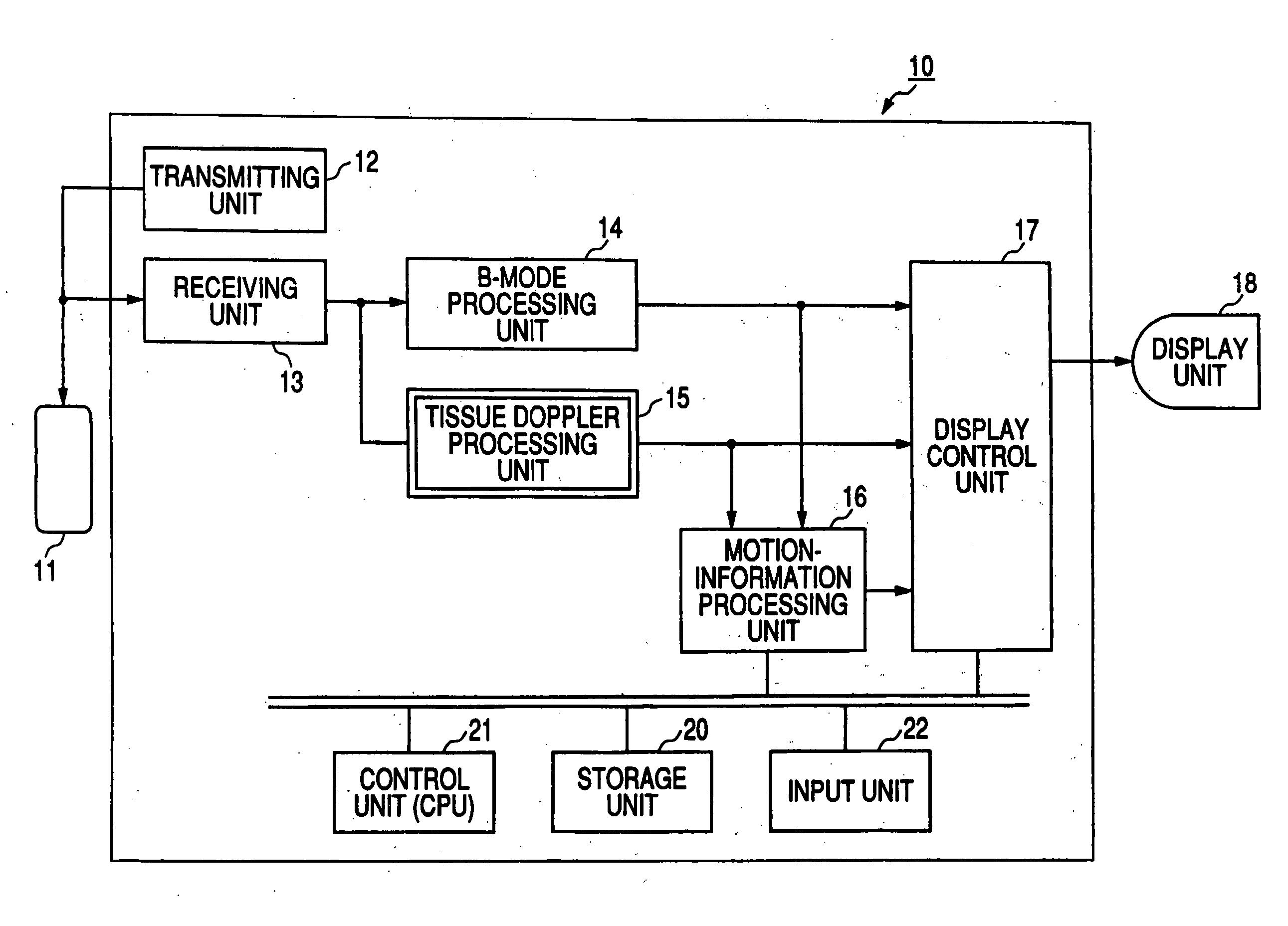
[0029]FIG. 1 is a block diagram of an ultrasonic diagnostic system 10 according to a first embodiment. The ultrasonic diagnostic system 10 includes an ultrasonic probe 11, a transmitting unit 12, a receiving unit 13, a B-mode processing unit 14, a tissue Doppler processing unit 15, a motion-information processing unit 16, a display control unit 17, a display unit 18, an input unit 19, a storage unit 20, a control unit 21, and an input unit 22.

[0030] The ultrasonic probe 11 includes a plurality of piezoelectric vibrators that generates ultrasonic waves in response to a drive signal from the transmitting unit 12, and converts reflected waves from a subject to electric signals; a matching layer provided to the piezoelectric...


PUM


Abstract

The ultrasonic diagnostic system estimates a desired time phase or one cycle period of a moving region (e.g., a heart) that repeats contraction and relaxation cyclically and which can be specified by a presystole, an end systole, a prediastole, an end diastole, and other clinical characteristics for one cycle of the moving region on the basis of the velocity information on multiple positions of the moving region which is obtained for each time phase. More specifically, assuming that, for example, the end systole phase=a time phase in which the myocardial velocity comes to zero or close to zero, the system calculates |myocardial velocity| for each time phase in a predetermined period, and estimates a time phase in which this value comes closest to zero as an end systole phase.

Description

CROSS-REFERENCE TO RELATED APPLICATIONS [0001] This is a Continuation Application of PCT Application No. PCT / JP2005 / 009966, filed May 31, 2005, which was published under PCT Article 21(2) in Japanese. [0002] This application is based upon and claims the benefit of priority from prior Japanese Patent Application No. 2004-161794, filed May 31, 2004, the entire contents of which are incorporated herein by reference.BACKGROUND OF THE INVENTION [0003] 1. Field of the Invention [0004] The present invention relates to an ultrasonic diagnostic system and a system and a method for ultrasonic imaging wherein the velocity of biological tissue such as cardiac muscle is estimated, and the estimated velocity information is processed to output local motion information of the tissue, thereby providing information useful in medical diagnosis, and in particular, it relates to a method for reducing the time and labor for operation by automatically detecting an end systole phase. [0005] 2. Description ...

Claims


Application Information

Patent Timeline
IPC IPC(8): A61B8/06A61B8/02A61B8/08G01S7/52G01S15/89
CPCA61B8/02A61B8/0883A61B8/485A61B8/488G01S7/52071G01S15/8979G06T7/20G06T2207/30048
Inventor ABE, YASUHIKO
Owner TOSHIBA MEDICAL SYST CORP
Why Eureka
Try Eureka