Method and apparatus for cathodic arc deposition of materials on a substrate

a cathodic arc and substrate technology, applied in vacuum evaporation coatings, electrolysis components, coatings, etc., can solve the problems of inability to apply a relatively thick coating (10-200 mils) and the cathode proximate the arc to undesirably melt, and achieve the effect of doubling the deposition ra

Active Publication Date: 2006-06-15
RTX CORP
View PDF7 Cites 11 Cited by
  • Summary
  • Abstract
  • Description
  • Claims
  • Application Information

AI Technical Summary

Benefits of technology

[0011] An advantage of the present invention method is that a cathodic arc deposition process is enabled that will permit thick coatings (e.g., 10-200 mils) to be applied to a substrate within a commercially practical period of time. The present invention method and apparatus enables deposition rates up to and beyond 4.0 mils per hour, thereby more than doubling the deposition rate possible with currently available cathodic arc coaters of which we are aware.
[0012] Another advantage of the present apparatus and method is that the integrity of the cathode is maintained during the erosion process. The present invention permits the cathode to be eroded using a high magnitude current without causing undesirable melting of the cathode, or appreciable undesirable macroscopic particle formation.
[0013] These and other objects, features and advantages of the present invention will become apparent in light of the detailed description of the best mode embodiment thereof, as illustrated in the accompanying drawings.

Problems solved by technology

Applying a relatively thick coating (10-200 mils) has heretofore not been practical because of the substantial time required to apply the coating at the deposition rate of currently available cathodic arc coaters (e.g., at 0.3 mil / hr, a 150 mil thick coating would take at least 500 hrs)
The increase in deposition rate is limited however, by the apparatus currently available.
Significantly increasing the current in currently available cathodic arc coaters is likely to cause the portion of the cathode proximate the arc to undesirably melt or increase the chance that undesirable macroscopic particles will be liberated.
In addition, most currently available cathodic arc coaters could not accommodate an appreciable increase in current without incurring significant damage.

Method used


Image

  • Method and apparatus for cathodic arc deposition of materials on a substrate
  • Method and apparatus for cathodic arc deposition of materials on a substrate
  • Method and apparatus for cathodic arc deposition of materials on a substrate

Examples


Embodiment Construction

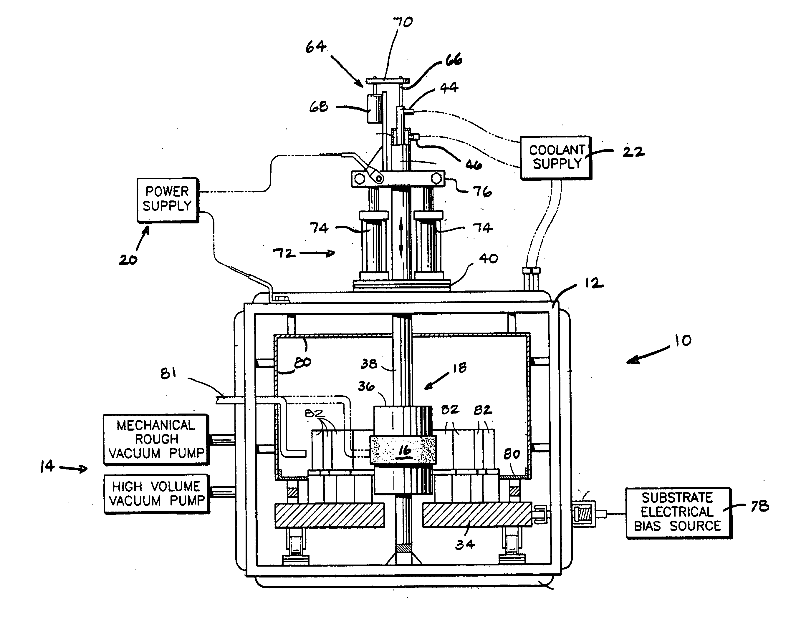
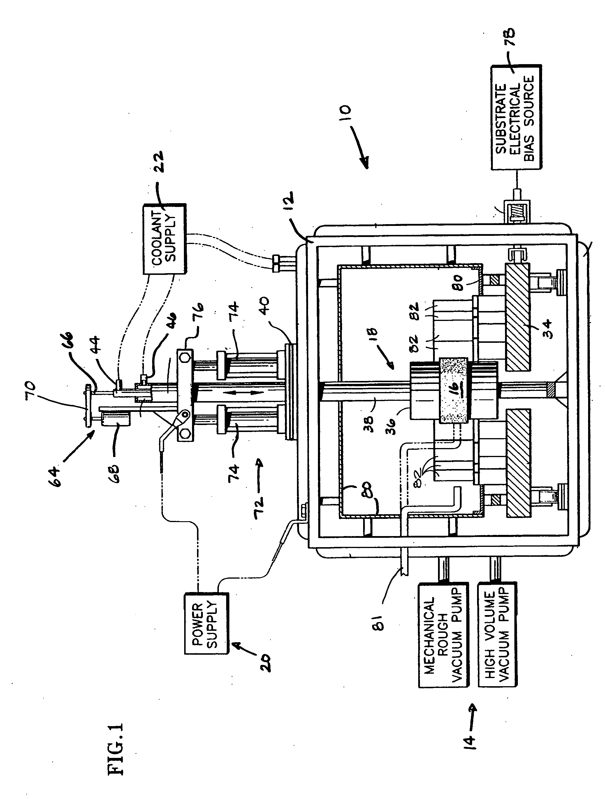
[0017] Referring to FIG. 1, an apparatus for cathodic arc vapor deposition on a substrate, hereinafter referred to as a “cathodic arc coater”10, is provided having a vessel 12, means 14 for maintaining a vacuum in the vessel 12, a cathode 16, a contactor 18, and means 20 for sustaining an arc of electrical energy between the cathode 16 and an anode. A coolant supply 22 maintains the coater 10 within acceptable temperatures by cycling coolant through cooling passages within the vessel 12 and contactor 18. In the preferred embodiment, the means 14 for maintaining a vacuum in the vessel 12 includes a mechanical rough vacuum pump and a high volume diffusion-type vacuum pump piped to the interior of the vessel 12. Other vacuum means may be used alternatively. A cathodic arc coater 10 as described in this paragraph is disclosed in U.S. Pat. No. 6,036,828, which is hereby incorporated by reference.

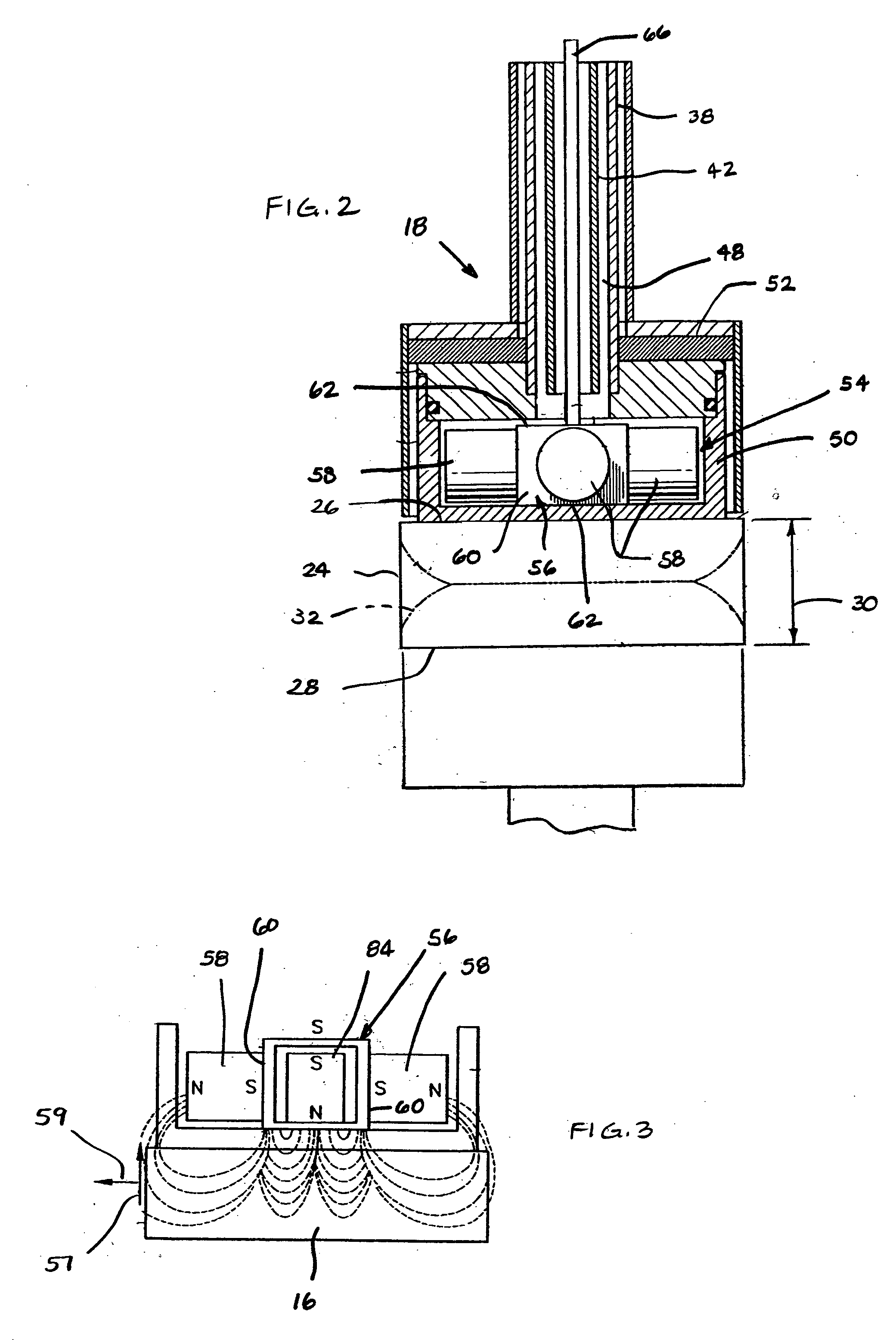
[0018] Referring to FIGS. 1-3, the cathode 16 is a substantially cylindrical disk having an ...


PUM

PropertyMeasurementUnit
deposition rateaaaaaaaaaa
thickaaaaaaaaaa
deposition rateaaaaaaaaaa

Abstract

A method for applying a coating by a cathodic is provided. The method includes the steps of: a) providing a cathodic arc coater that includes a power source and utilizes a disk-shaped cathode, the cathode having an evaporative surface extending between a first end surface and a second end surface, wherein the evaporative surface has an area; b) determining a maximum acceptable power density for the evaporative surface; and c) applying a magnitude of electrical current from the power source to the cathode, wherein the electrical current magnitude divided by the area is equal to or less than the maximum acceptable power density for the evaporative surface.

Description

BACKGROUND OF THE INVENTION [0001] 1. Technical Field [0002] This invention relates to apparatus for vapor deposition of coatings in general, and to cathodic arc vapor deposition apparatus in particular. [0003] 2. Background Information [0004] Vapor deposition as a means for applying a coating to a substrate is a known art that includes processes such as chemical vapor deposition, physical vapor deposition, and cathodic arc vapor deposition. Chemical vapor deposition involves introducing reactive gaseous elements into a deposition chamber containing one or more substrates to be coated. Physical vapor deposition involves providing a source material and a substrate to be coated in an evacuated deposition chamber. The source material is converted into vapor by an energy input, such as heating by resistive, inductive, or electron beam means. [0005] Cathodic arc vapor deposition involves a source material and a substrate to be coated placed in an evacuated deposition chamber. The chamber...

Claims


Application Information

Patent Timeline
Patent Type & Authority Applications(United States)
IPC IPC(8): C23C14/32
CPCC23C14/325H01J37/32055H01J37/32614C23C14/54
Inventor BEERS, RUSSELL A.KASULE, ASUMINICOLLINS, KEVIN LEE
Owner RTX CORP
Why Eureka
Try Eureka