Method of rtm molding

a molding method and rtm technology, applied in the direction of lamination, lamination apparatus, chemical equipment and processes, etc., can solve the problems of difficult to push out voids in the side directions, limit the distance in which the thickness direction of the substrate can be impregnated, and the inability to predetermined impregnation, etc., to achieve good resin impregnation properties, improve surface quality, and increase the effect of lightweight properties

Active Publication Date: 2006-06-15
TORAY IND INC +1
View PDF9 Cites 67 Cited by
  • Summary
  • Abstract
  • Description
  • Claims
  • Application Information

AI Technical Summary

Benefits of technology

[0020] Accordingly, an object of the present invention is to provide a method of RTM molding (method for producing an FRP) which can solve the above-described various problems in the conventional methods, which can mold even a thick FRP structural material with a good resin impregnation property, and which can realize improvement of the surface quality, increase of the lightweight property and achievement of an excellent strength.

Problems solved by technology

As the problem in the above-described molding method, although resin distribution media are disposed on both surfaces of the reinforcing fiber substrate, because the resin impregnation is carried out basically from one surface side relatively to the reinforcing fiber substrate, there is a limit in a distance capable of being impregnated in the thickness direction of the substrate.
Therefore, if the reinforcing fiber substrate is too thick, a predetermined impregnation becomes impossible.
In the above-described molding method, however, because the resin distribution media having substantially same shape and property are disposed on both surfaces, when merely the resin is impregnated from the both surface sides, the resin is impregnated in the thickness direction of the substrate simultaneously and in a same manner, voids are hard to be pushed out in the side directions, and the voids are likely to be enclosed in the substrate.
If the voids are enclosed, it is difficult to obtain a target property of a molded product.
Further, as another problem on the above-described molding method, there is a problem that it is difficult to obtain a good flatness on the design surface of the molded product.
However, if the resin distribution media having such a relatively large surface irregularity are disposed on both surfaces of the reinforcing fiber substrate and the molding is carried out in this condition, the relatively large surface irregularity of the resin distribution medium is reflected to the design surface which is one surface of the molded product.
As a result, the designability is damaged and an irregularity is formed on the surface of the molded product, and therefore, there is a problem that the properties such as aerodynamic property decrease.
In order to solve such problems, it is considered to use a resin distribution medium having a small surface irregularity, but if done so, the resistance for gas permeation becomes too great, and a target resin distribution property cannot be obtained.
Further, because the gas permeation from the reinforcing fiber substrate at the time of evacuation also deteriorates, the vacuum degree does not increase, and it becomes difficult to completely impregnate the resin in the thickness direction particularly for a thick substrate.
Therefore, in the conventional method wherein substantially same resin distribution media are disposed on both surfaces of a reinforcing fiber substrate, it is difficult to achieve both of increase of the resin impregnation property and improvement of the surface property of a molded product, and it becomes particularly difficult in the molding using a thick reinforcing fiber substrate.
In the above-described method, when the resin injection is carried out at a so-called high Vf condition where the fiber volume content (Vf) of the reinforcing fiber substrate is 55% or more, namely, at a condition where a gap between reinforcing fibers is small, although the fiber volume content of a final molded product itself becomes high, the impregnation property of the resin into the molded product is poor.
Namely, the resin impregnation property and the fiber volume content Vf are in a relationship opposite to each other, and it is difficult to achieve both improvement of the resin impregnation property and increase of the fiber volume content together.
Moreover, although it is preferred depending on a molded product to control the fiber volume content from the necessity of stabilization of the quality, it is also difficult to satisfy such a requirement.
Further, although usually the reinforcing fiber substrate is formed as a laminate of a plurality of reinforcing fiber materials in order to obtain an FRP molded product with a predetermined thickness, as to the thickness direction, that is, as to the direction perpendicular to the lamination surface in the reinforcing fiber material laminate, the resistance against the resin flow is generally high, and there is a limit in the reaching distance of the resin being impregnated in the thickness direction of the substrate.
Therefore, in a case where it is required to increase the number of lamination of the reinforcing fiber materials such as a case of planning to mold a high-strength product, it may be difficult to completely impregnate the resin into the corners of the reinforcing fiber material laminate, and consequently, an FRP structural material having a certain thickness or more substantially cannot be molded.

Method used


Image

  • Method of rtm molding
  • Method of rtm molding
  • Method of rtm molding

Examples


example 1

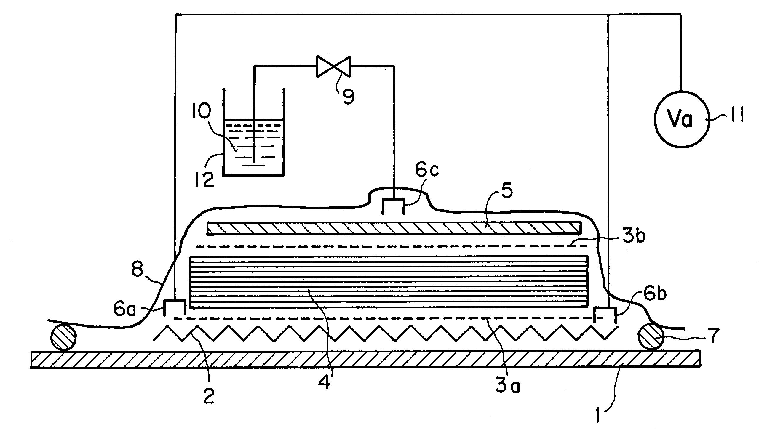
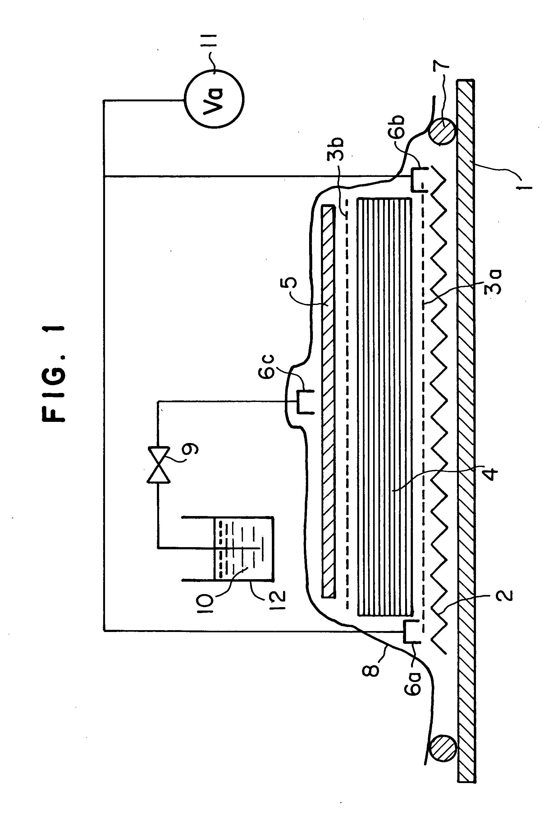
[0150] In the molding apparatus for RTM shown in FIG. 1, breather 2 (glass fiber surface mat, weight: 80 g / m2) was placed on the molding surface of mold 1, evacuation gates 6a, 6b were disposed at both end portions, and vacuum pump was connected. Peel ply 3a was disposed on breather 2, and thereon, reinforcing fiber substrate 4 comprising carbon fiber woven fabrics (produced by Toray Industries, Inc., plain weave fabric CO6343 using carbon fibers T300, weight: 200 g / m2) laminated by 120 plies was disposed. At that time, although peel ply 3a between breather 2 and reinforcing fiber substrate 4 may be omitted, this structure is allowed at a premise that the breather is left in a product after molding, and in such a case, a carbon fiber mesh woven fabric is desirable as the breather.

[0151] Peel ply 3b was disposed on reinforcing fiber substrate 4, thereon resin distribution medium 5 of a polypropylene mesh material (produced by Tokyo Polymer Corporation, “Netron”TSX-400P) was disposed...

example 2

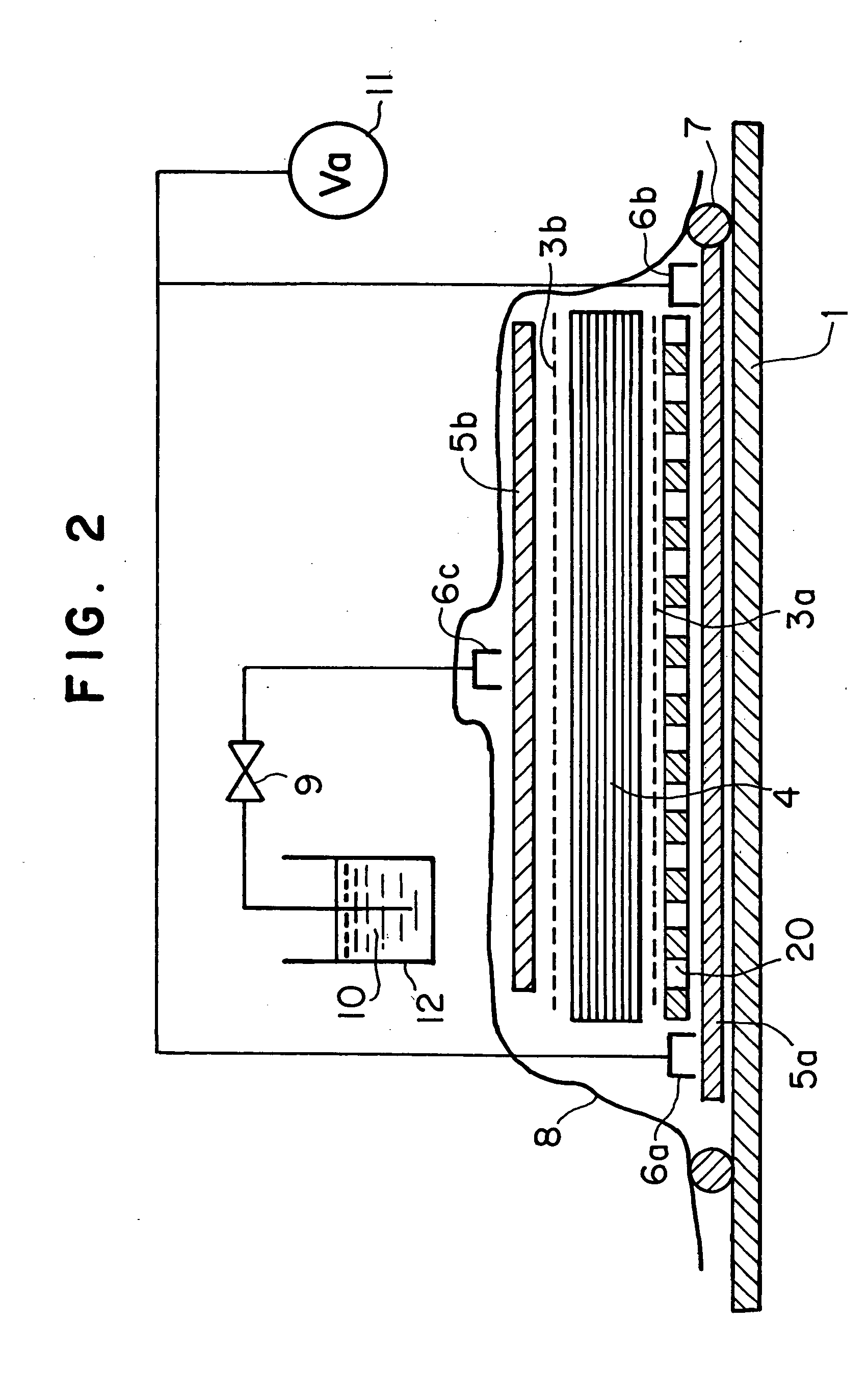
[0152] In the molding apparatus for RTM shown in FIG. 2, on the molding surface of mold 1, medium 5a of a polypropylene mesh material (produced by Tokyo Polymer Corporation, “Netron”TSX-400P) was disposed, and on the circumferential portion thereof, evacuation gates 6a, 6b were placed, and they were connected to vacuum pump 11. Porous sheet 20 (stainless steel punching metal with a thickness of 0.2 mm, in which holes each having a diameter of 1 mm were processed at a pitch of 10 mm) was disposed on the medium 5a, thereon peel ply 3a was disposed, and thereon, reinforcing fiber substrate 4 comprising carbon fiber woven fabrics (produced by Toray Industries, Inc., plain weave fabric CO6343 using carbon fibers T300, weight: 200 g / m2) laminated by 120 plies was disposed.

[0153] Peel ply 3b was disposed on reinforcing fiber substrate 4, thereon medium 5b was disposed, and thereon resin injection port 6c was disposed and it was connected to resin pot 12 via valve 9 as a resin injection ga...

example 3

[0154] In the molding apparatus for RTM shown in FIG. 3, using the mold processed with #-type grooves 30 for resin distribution (a groove having a rectangular cross section with a width of 1 mm and a depth 3 mm and the pitch of the grooves is 8 mm), resin pot 12 was connected to the grooves via valve 9. Porous sheet 20 (stainless steel punching metal with a thickness of 0.2 mm, in which holes each having a diameter of 1 mm were processed at a pitch of 10 mm) was disposed on the molding surface, thereon peel ply 3a was disposed, and thereon, reinforcing fiber substrate 4 comprising carbon fiber woven fabrics (produced by Toray Industries, Inc., plain weave fabric CO6343 using carbon fibers T300, weight: 200 g / m2) laminated by 120 plies was disposed. Peel ply 3b was disposed on reinforcing fiber substrate 4, thereon medium 5 of a polypropylene mesh material (produced by Tokyo Polymer Corporation, “Netron”TSX-400P) was disposed, and thereon, evacuation gate 6 was placed and it was conn...


PUM

PropertyMeasurementUnit
lengthaaaaaaaaaa
viscosityaaaaaaaaaa
thicknessaaaaaaaaaa

Abstract

A method of RTM molding wherein a reinforcing fiber substrate is placed in a mold, each of a first and a second resin distribution media exhibiting a resin flow resistance lower than the resistance of the reinforcing fiber substrate is placed on each surface of the reinforcing fiber substrate, and the inside of the mold is evacuated and a resin is injected into the mold to thereby impregnate the reinforcing fiber substrate with the resin injected, characterized in that the first resin distribution medium exhibits a resin flow resistance lower than that of the second resin distribution medium, and the evacuation is carried out through the second resin distribution medium while the resin is injected through the first resin distribution medium. The method can be advantageously employed for producing, in particular, FRP structure which is thick and excellent in designability, lightweight property and / or strength.

Description

TECHNICAL FIELD OF THE INVENTION [0001] The present invention relates to improvement of a method of Resin Transfer Molding (hereinafter, referred to as “RTM”) for molding a structural material of a fiber reinforced plastic (hereinafter, referred to as “FRP”), and specifically, to a method of RTM molding in which it is possible to mold a thick material, and further, it is possible to improve a quality of surface property or to increase a fiber volume content (hereinafter, also referred to as “Vf”) of an FRP molded material to be molded. Although the title of the present invention is referred to as “method of RTM molding” in this specification, the technical concept according to the present invention includes this molding method due to RTM itself and a method for producing an FRP molded material using the molding method. BACKGROUND ART OF THE INVENTION [0002] Although FRP has been used in various fields, as a method for producing an FRP structural material, general is a so-called prep...

Claims


Application Information

Patent Timeline
Patent Type & Authority Applications(United States)
IPC IPC(8): B29C43/10B29C70/44B29C70/54
CPCB29C70/443B29C70/547B29C70/548B29C70/68B29C45/0005
Inventor SEKIDO, TOSHIHIDEKITAOKA, KAZUAKIODANI, HIROSHINISHIYAMA, SHIGERUSHIMIZU, MASAHIKO
Owner TORAY IND INC
Why Eureka
Try Eureka