Eureka AIR delivers breakthrough ideas for toughest innovation challenges, trusted by R&D personnel around the world.

Drive arrangement for activating the hatch of a motor vehicle

Inactive Publication Date: 2006-06-15
BROSE SCHLIESSSYSTEME GMBH & CO KG
View PDF3 Cites 11 Cited by
  • Summary
  • Abstract
  • Description
  • Claims
  • Application Information

AI Technical Summary

Benefits of technology

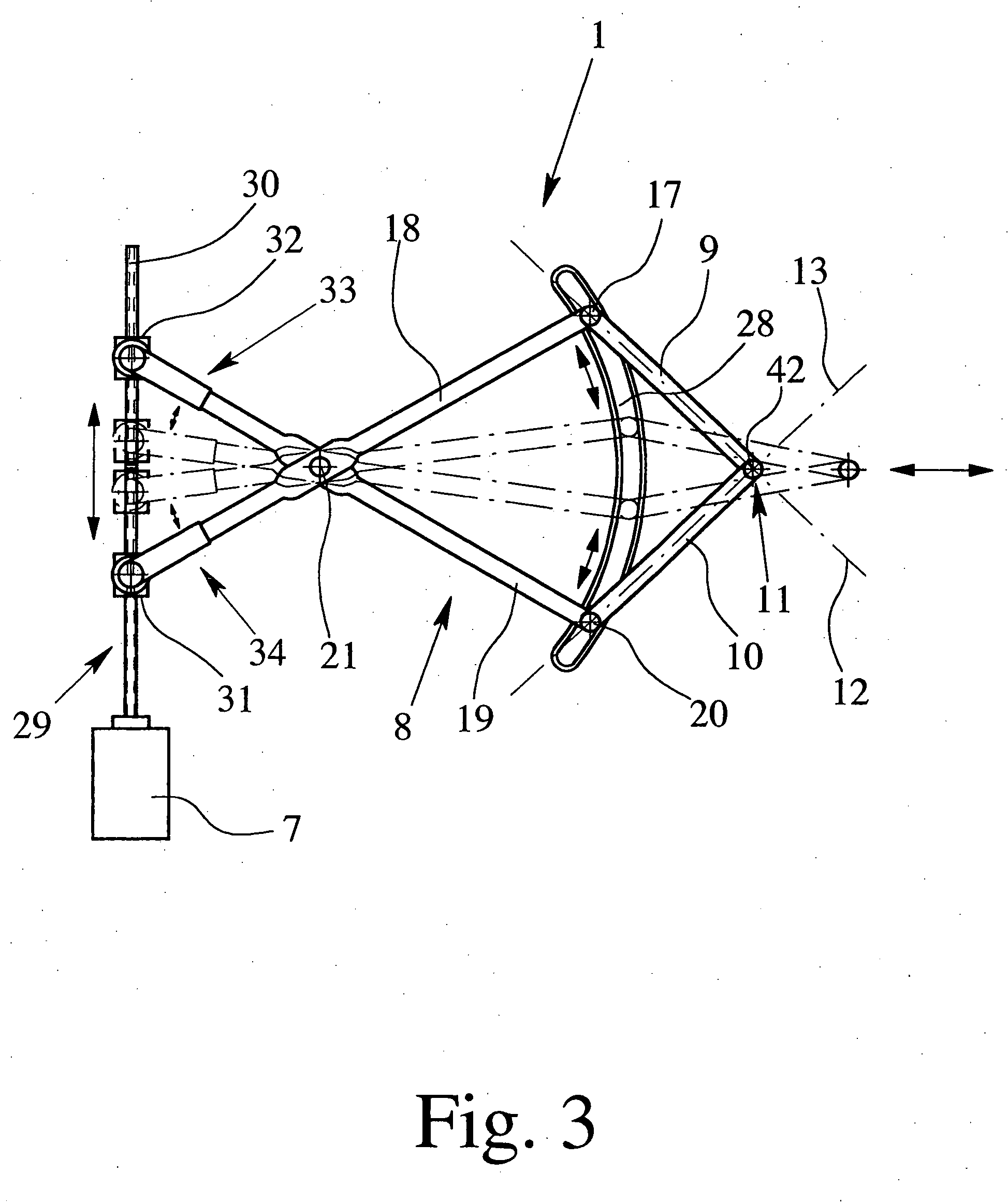
[0010] Here, the finding is important that, with a corresponding arrangement of the driven lever, the axial dynamic effect of one driven lever against the axial dynamic effect of the other driven lever can be cancelled. The actuating motions of the two driven levers can be easily controlled so that an efficient and simultaneously durable drive arrangement can be implemented.
[0011] The two driven levers are used to transmit pushing forces and / or pulling forces on the hatch, the lines of dynamic effect of the two driven levers forming an included angle with one another which corresponds to the respective position of the hatch. This angle is called the driven angle below. In preferred configurations, the angle bisector of the driven angle lies essentially in a vertically aligned plane which intersects the central lengthwise axis of the motor vehicle. Furthermore, the driving force acting on the hatch from the drive arrangement does not have any component in the direction of the hatch axis. As a result, complete elimination of the axial dynamic effect of the drive arrangement on the hatch is ensured.
[0013] An especially durable and at the same time compact configuration implements the drive-engineering coupling between the drive motor and the transmission linkage in an especially simple manner by the ends of the drive levers, which ends are facing away from the respective driven levers, each being equipped with an arc-shaped toothed segment which is aligned around the pivot axis of the drive levers. One toothed segment has an external tooth system and the other toothed segment has an internal tooth system which faces this external tooth system, the drive motor having a rotatable driving pinion that engages the two toothed segments by drive engineering.
[0014] A further preferred configuration of the drive arrangement with a linear drive, depending on the application, can lead to optimum use of installation space and to optimum transmission behavior of the transmission linkage. By having the ends of the drive levers which face away from the respective driven levers coupled to the linear drive by drive engineering, the transmission linkage can be easily designed such that both the stress of spindle-nut transmission and the associated wear are low. The two connecting joints between the drive lever and the driven lever are guided here on a corresponding guide rail.

Problems solved by technology

This component of the driving force basically leads specifically to undesirable loading of the components involved.
In any case, the use of a spindle-nut transmission is associated with high implementation costs, poor durability and especially high wear.
Furthermore, the actuating speed can only be increased to a limited degree.
The efficiency of the drive arrangement is thus altogether limited.

Method used


Image

  • Drive arrangement for activating the hatch of a motor vehicle
  • Drive arrangement for activating the hatch of a motor vehicle
  • Drive arrangement for activating the hatch of a motor vehicle

Examples


Embodiment Construction

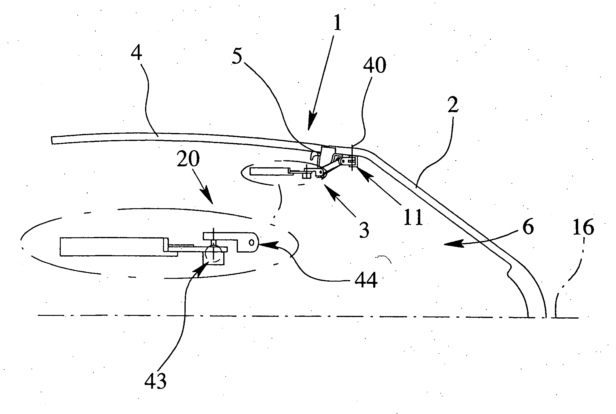
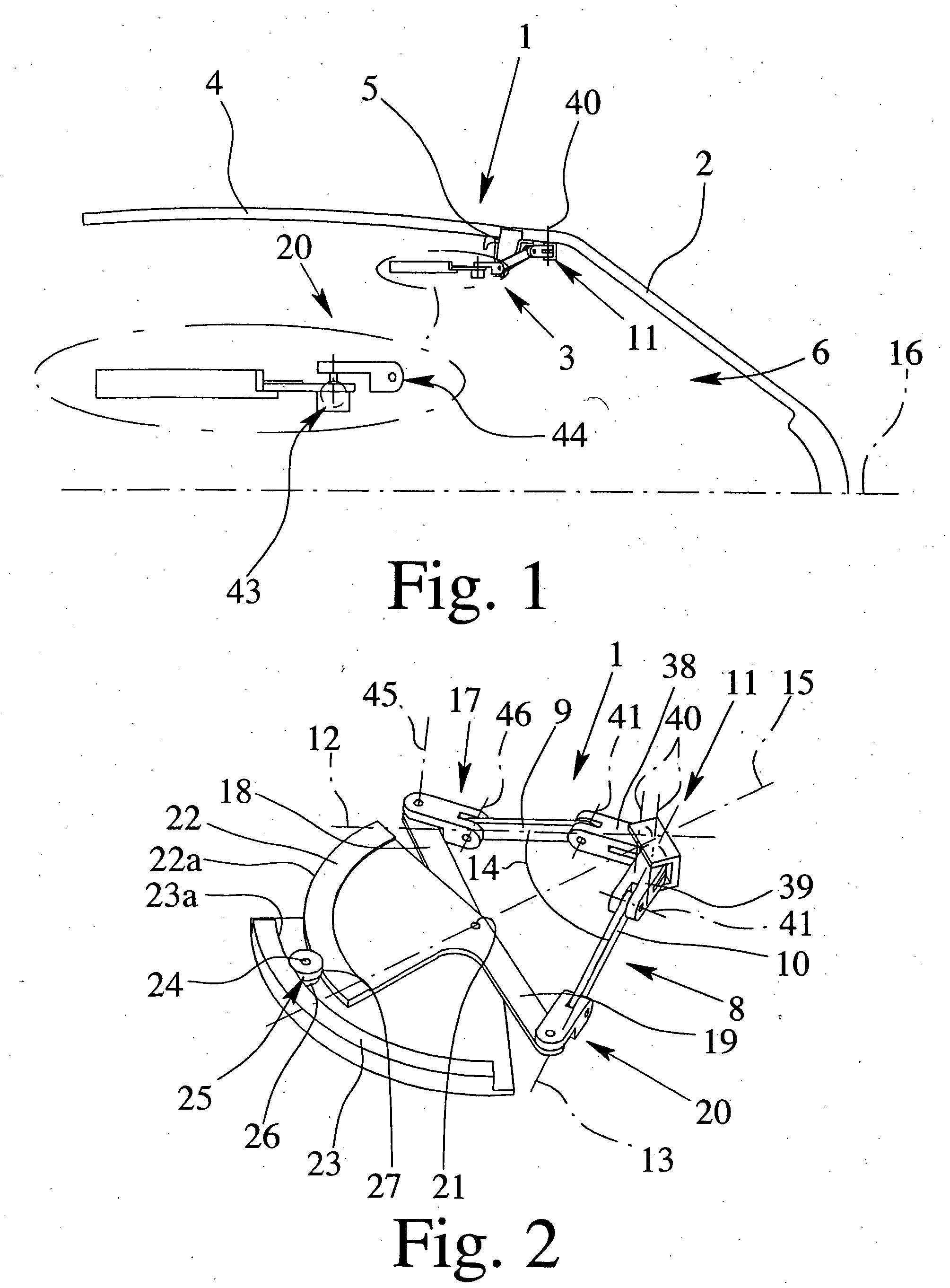
[0024] The drive arrangement 1 shown in FIG. 1 is in the installed state. It is used to actuate the hatch 2 of the illustrated motor vehicle and has a drive 3 for this purpose. Basically, it can also be provided that there are several drives 3, preferably two drives 3, each preferably laterally arranged, for actuating the hatch 2.

[0025] The hatch 2 is coupled to the body 4 of the motor vehicle to pivot around the hatch axis 5, by which the hatch opening 6 of the body 4 can be closed. It should be pointed out that, as described above, the term “hatch” should be understood comprehensively here. Especially with respect to optimum use of installation space, the drive arrangement 1 of the invention, however, can be applied especially advantageously to the rear hatch or the trunk lid of a motor vehicle.

[0026] To produce driving motions, the drive 3 is equipped with a drive motor 7 and a transmission linkage 8 connected on the output side of the drive motor 7. Movement of the hatch 2 bet...


PUM


Abstract

A drive arrangement for actuating a hatch of a motor vehicle with a drive for producing driving having a drive motor for producing movement of the hatch between an open position and a closed position and having a transmission linkage connected on the output side of the motor. The transmission linkage has a first driven lever and a second driven lever for transmission of pushing forces and / or pulling forces to the hatch, and the driven levers, in the installed state, converge on a joint arrangement which is located on the hatch and are coupled to it by drive engineering in a manner such that the lines of dynamic effect of the two driven levers form an included angle with one another which corresponds to the respective position of the hatch.

Description

BACKGROUND OF THE INVENTION [0001] 1. Field of Invention [0002] This invention relates to a drive arrangement for actuating the hatch of a motor vehicle with a drive, the hatch being coupled to the body to pivot around a hatch axis, and in this way, the hatch opening of the body can be closed. The drive for producing the drive motions has a drive motor and transmission linkage connected on the output side, and movement of the hatch between an open position and a closed position can be effected with a drive motion. The invention also relates to a hatch arrangement, especially a rear hatch arrangement of a motor vehicle with the aforementioned drive arrangement. [0003] 2. Description of Related Art [0004] The term “hatch” of a motor vehicle is to be understood comprehensively here. Accordingly, it includes not only the rear hatch, the trunk lid, the hood or the cargo space hatch of a motor vehicle but, for example, also the side doors or a lifting sunroof of a motor vehicle, if presen...

Claims


Application Information

Patent Timeline
IPC IPC(8): B60J5/10
CPCB60J5/101E05Y2201/726E05F15/63E05F15/619E05F15/622E05Y2900/546
Inventor GULER, MEHMET
Owner BROSE SCHLIESSSYSTEME GMBH & CO KG
Why Eureka
Eureka Blog
Learn More