Vehicle-brake control unit

a technology of brake pedal and control unit, which is applied in the direction of braking system, braking components, transportation and packaging, etc., can solve the problem of not maintaining the optimum braking force relative to the brake pedal pressur

Inactive Publication Date: 2006-06-15
ADVICS CO LTD
View PDF4 Cites 28 Cited by
  • Summary
  • Abstract
  • Description
  • Claims
  • Application Information

AI Technical Summary

Benefits of technology

[0033] For the vehicle braking device having a longitudinal pipe arrangement, when only the system for the two rear wheels of the pressure control section fails, so that the pressurization for the system for the two rear wheels cannot be generated, the total pressurizing hydraulic braking force becomes smaller than that “when the pressure control section is normal” and more than half of that “when the pressure

Problems solved by technology

Thus, in this case, the characteristic of the total braking force relative to the brake-pedal pressure does not agree with a predet

Method used


Image

  • Vehicle-brake control unit
  • Vehicle-brake control unit
  • Vehicle-brake control unit

Examples


first embodiment

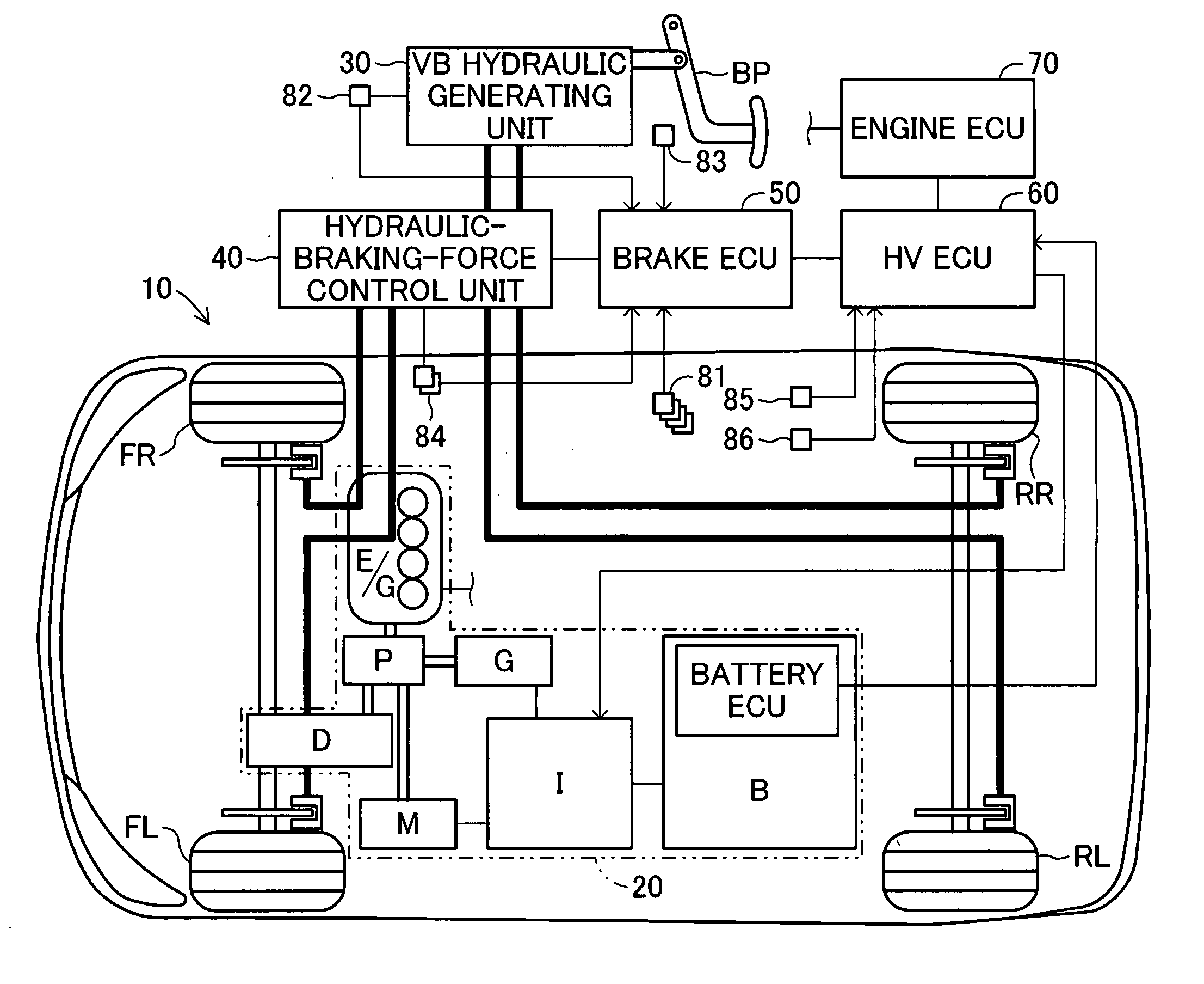
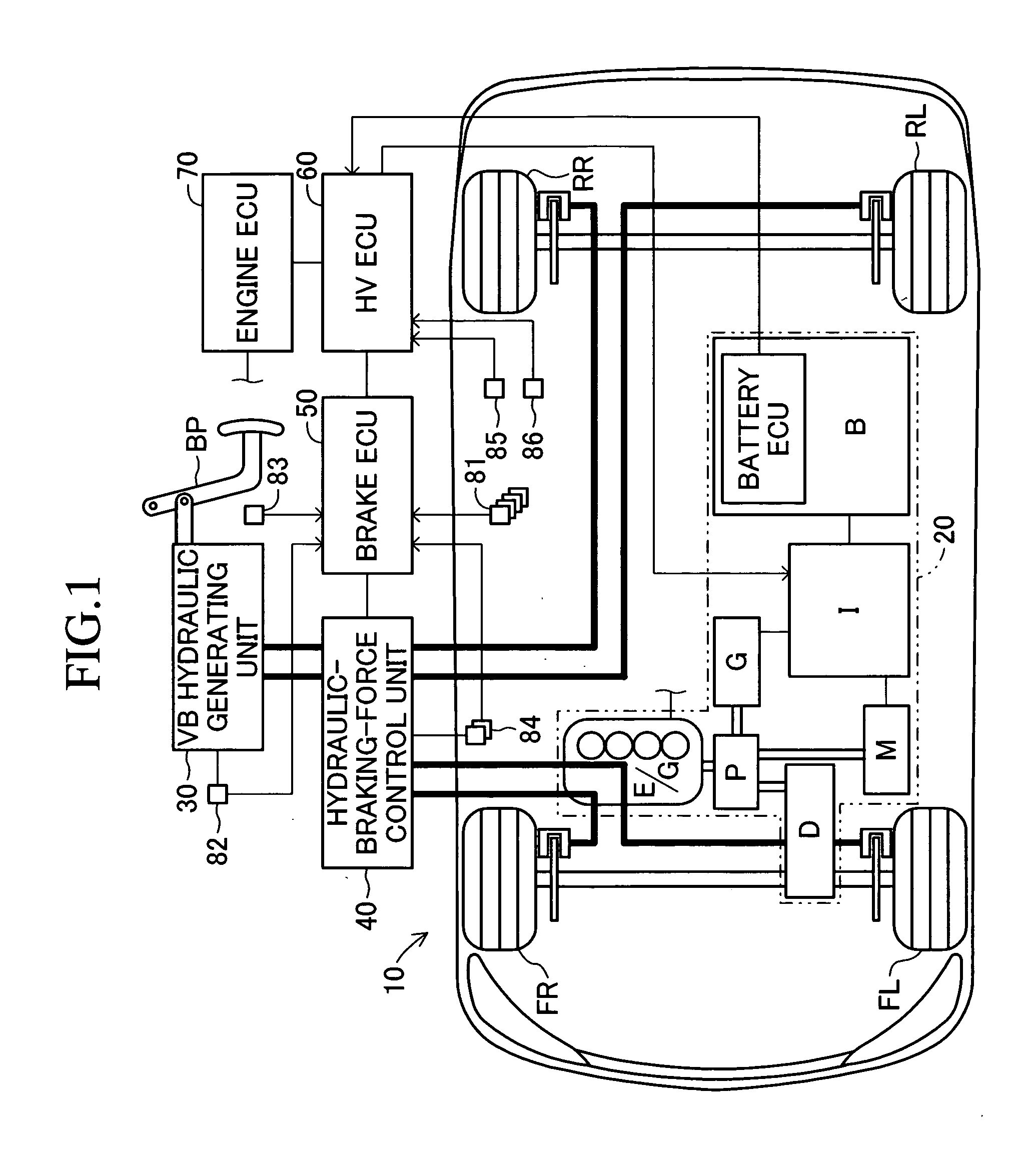
[0047]FIG. 1 is a schematic diagram of a vehicle equipped with a vehicle braking device 10 according to a first embodiment of the invention. The vehicle has two systems of brake hydraulic circuits (that is, a cross pipe arrangement), a system for the front right wheel and the rear left wheel and a system for the front left wheel and the rear right wheel, and is a what-is-called front-wheel-drive hybrid vehicle that uses a combination of an engine and a motor as power supply.

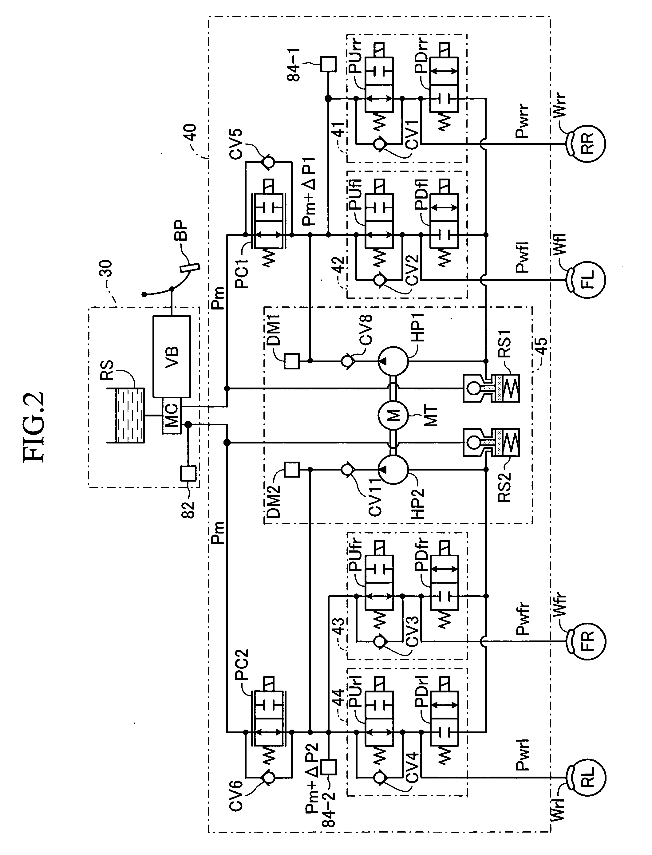
[0048] The vehicle braking device 10 includes a hybrid system 20 having two kinds of power supplies, an engine E / G and a motor M; a vacuum-booster hydraulic-pressure generating unit (hereinafter, referred to as a VB hydraulic generating unit 30) that generates a brake hydraulic pressure corresponding to the brake-pedal operation by a driver; a hydraulic-braking-force control unit 40 that controls the hydraulic braking forces of the wheels (specifically, wheel-cylinder pressures); a electronic brake control unit ...

second embodiment

Actual Operation of Second Embodiment

[0153] The actual operation of the vehicle braking device according to the second embodiment will be described. The HV ECU 60 of this device executes the routine shown in FIG. 8 for the HV ECU 60 of the first embodiment. The brake ECU 50 of this device executes the routine shown in the flowchart of FIG. 12, in place of the routine of FIG. 7 executed by the brake ECU 50 of the first embodiment. The routine shown in FIG. 12 specific to the second embodiment will be described hereinbelow.

[0154] The brake ECU 50 of the device repeats the routine of controlling the hydraulic braking force, shown in FIG. 12, at a fixed interval (a time interval Δt, e.g., 6 msec). In the routine of FIG. 12, the same steps as those of FIG. 7 are given the same step numbers as those of FIG. 7.

[0155] Accordingly, the brake ECU 50 starts the operation from step 700 at a predetermined time. Assuming that the brake pedal BP is in operation, the brake ECU 50 executes the ope...


PUM


Abstract

The unit controls a linear-valve-pressure-difference braking force and a regenerative braking force so that a total braking force obtained by adding a complementary braking force that is “the sum of the increments of the respective hydraulic braking forces by linear-valve pressure differences generated by linear solenoid valves disposed for their respective systems (linear-valve-pressure-difference braking force) and a regenerative braking force” to a hydraulic braking force (VB hydraulic braking force) based on a master-cylinder pressure output from a master cylinder reaches a target value for a brake-pedal pressure. For example, for a vehicle equipped with a cross pipe arrangement, when one of the linear solenoid valves fails, the linear-valve pressure difference of a normal linear solenoid valve is set to a value as twice as large as that when both of the linear solenoid valves are normal.

Description

BACKGROUND OF THE INVENTION [0001] 1. Field of the Invention [0002] The present invention relates to a vehicle-brake control unit. [0003] 2. Description of the Related Art [0004] Conventionally, it is known in the art to provide an automatic braking device that automatically controls the hydraulic pressure of a wheel cylinder independently of the operation of a brake operating member such as a brake pedal by a driver. For example, an automatic braking device described in Japanese Unexamined Patent Application Publication No. 2004-9914 includes two systems of brake hydraulic circuits, a system for the front right wheel and the rear left wheel and a system for the front left wheel and the rear right wheel. [0005] The device includes a master cylinder that generates basic hydraulic pressure (master-cylinder pressure and vacuum-booster pressure) based on the operation of a vacuum booster according to the brake-pedal operation, independently of the brake-pedal operation by a driver; a hy...

Claims


Application Information

Patent Timeline
IPC IPC(8): B60T8/64B60K6/445B60T8/17B60T8/92B60W10/18B60W20/00
CPCB60K6/445B60T1/10B60T13/586B60T2270/604B60W10/08B60W10/184B60W20/00B60W30/18127Y02T10/6239Y02T10/62B60W20/13B60W10/18
Inventor KOKUBO, KOICHISAITO, SHIGERUMATSUURA, MASAHIROSENGOKU, YUJI
Owner ADVICS CO LTD
Why Eureka
Try Eureka