Power supply for LED signal

Active Publication Date: 2006-06-15
GE LIGHTING SOLUTIONS LLC
View PDF5 Cites 58 Cited by
  • Summary
  • Abstract
  • Description
  • Claims
  • Application Information

AI Technical Summary

Benefits of technology

[0012] The EMC filter module contains an arrangement of X2-and Y-capacitors, inductors and common mode chokes to reduce conducted electromag

Problems solved by technology

However, when dimmed the lamp must sti

Method used


Image

  • Power supply for LED signal
  • Power supply for LED signal
  • Power supply for LED signal

Examples


Embodiment Construction

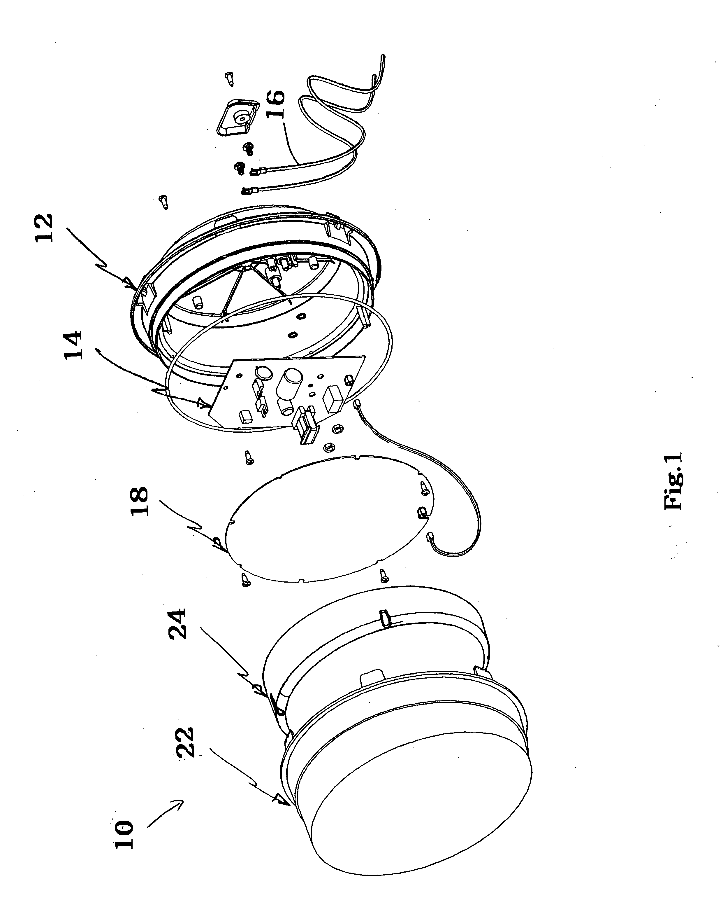
[0024] A LED traffic signal 10 comprises a housing 12, a power supply 14, wires 16, a printed circuit board 18, at least one LED 20 and an outer shell or cover 22. In addition, the signal 10 may include a mask (not shown) and / or optical element 24. For example, an arrow signal preferably uses an arrow shaped mask (not shown). Preferably, the housing is moisture and dust resistant. Preferably, the optical element 24 and outer shell 22 are made of UV stabilized polycarbonate.

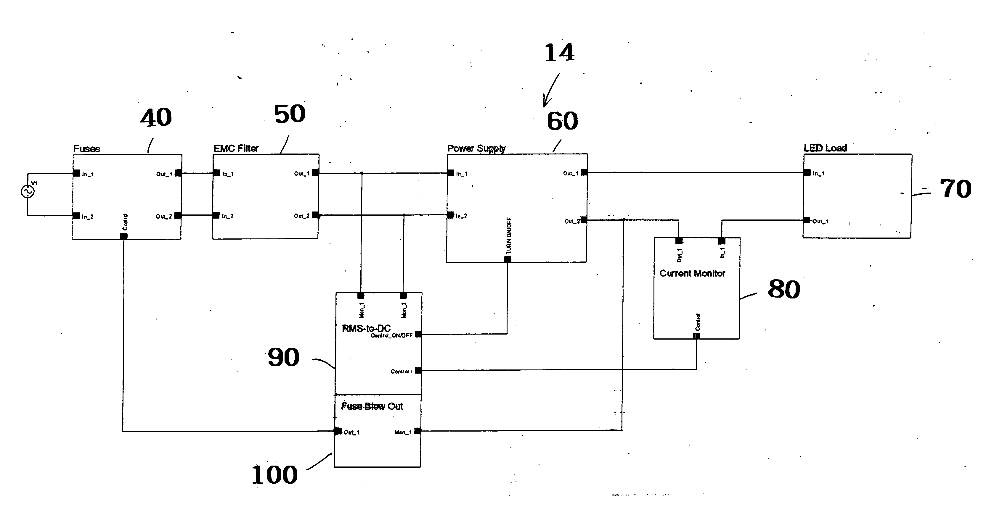
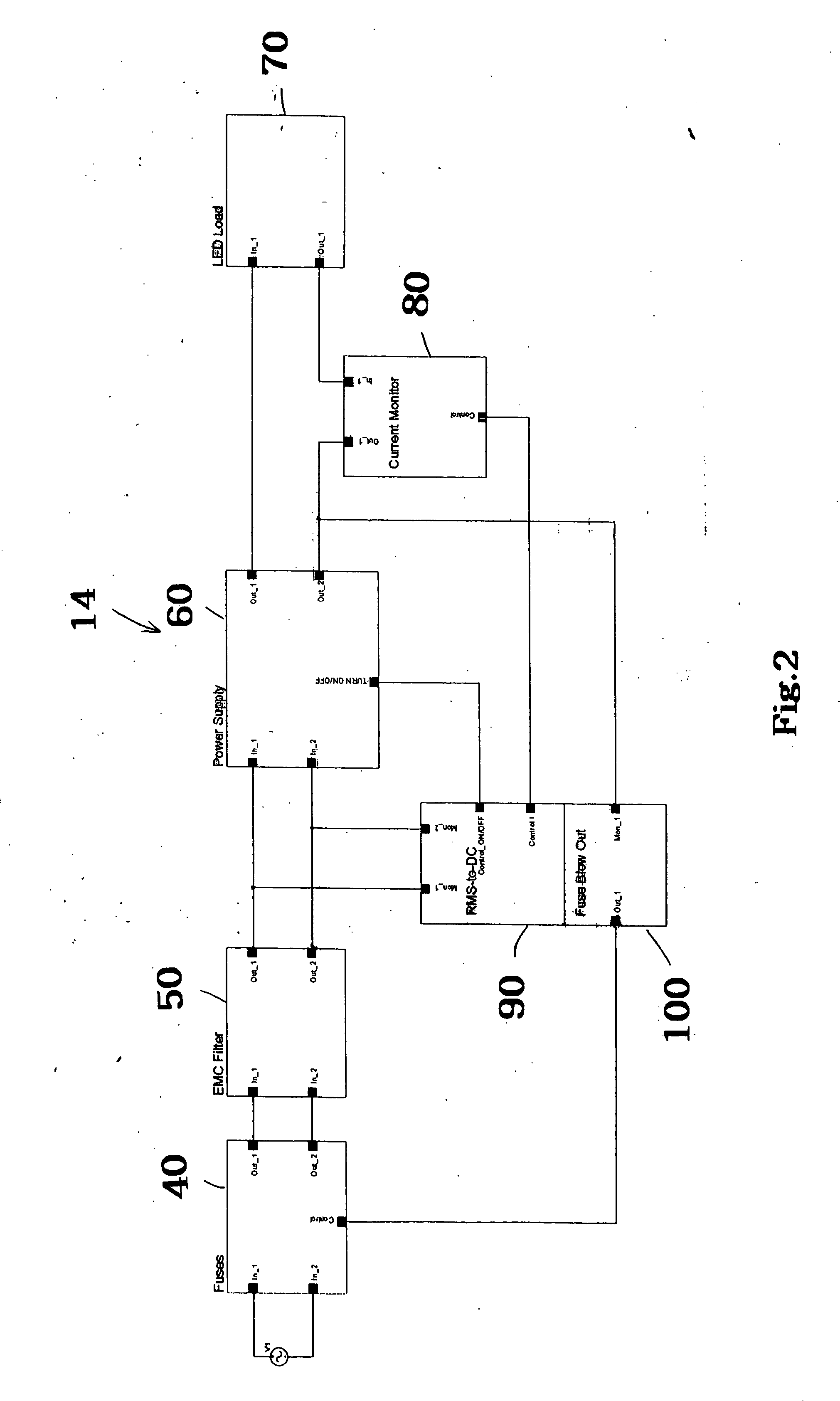
[0025] A block diagram of the power supply system 14 is shown in FIG. 2. Each module will be explained in detail below. The power supply system includes 14 a novel system to control the light intensity of a LED traffic signal 10 to conform to a predetermined pattern, depending on the input voltage root mean square (RMS) value. The input voltage is changed by acting on the amplitude of the sine wave or by using a triac and controlling the angle of fire. Preferably, the signal 10 operates at a voltage range of abou...


PUM


Abstract

A power supply for a Light Emitting Diode (LED) traffic signal that controls the light intensity. The light intensity conforms to a predetermined pattern based on the input voltage root mean square value (Vrms). The input voltage is changed by acting on the amplitude of the sine wave or by using a triac and controlling the angle of fire. The power supply comprises a fuse module, an electromagnetic compatibility filter module, a power supply module, a LED load module, a current monitor module, a RMS-DC conversion module and a fuse blow out module.

Description

BACKGROUND OF THE INVENTION [0001] 1. Field of the Invention [0002] The present inventions relates to traffic signals. More particularly, the present invention relates to power supplies for light emitting diode (LED) traffic signals. [0003] 2. Description of the Related Art [0004] Traffic signal lamps typically use either incandescent or LED lamps. LED traffic signals are more reliable, more mechanically stable, safer, more energy efficient and more environmentally friendly than incandescent lamps. Thus, LED traffic signals are gaining in popularity. [0005] LED traffic signals are typically used as a replacement for an incandescent bulb traffic signals. They may also be used in new traffic installations. Driven by stable current and voltage levels produced by switching power supplies, LED traffic signals consume relatively low amounts of power and have extremely long lifetimes compared to standard incandescent bulbs. Whether the signals is being retrofit into an existing traffic sig...

Claims


Application Information

Patent Timeline
IPC IPC(8): H05B37/02
CPCH05B33/0824H05B33/0884H05B45/00H05B45/44H05B45/52H05B45/54
Inventor BOURGAULT, JEAN SIMON
Owner GE LIGHTING SOLUTIONS LLC
Why Eureka
Try Eureka