
Evanescent microwave probe with enhanced resolution and sensitivity

a microwave probe and enhanced technology, applied in the field of evanescent wave probes, can solve the problems of reducing the sensitivity of the probe system and reducing the quality of the probe, so as to reduce the effect of residual far field radiation, improve the sensitivity and resolution, and reduce the quality factor (q) of the resonator

Inactive Publication Date: 2006-06-15
INTEMATIX
View PDF7 Cites 52 Cited by
  • Summary
  • Abstract
  • Description
  • Claims
  • Application Information

AI Technical Summary

Benefits of technology

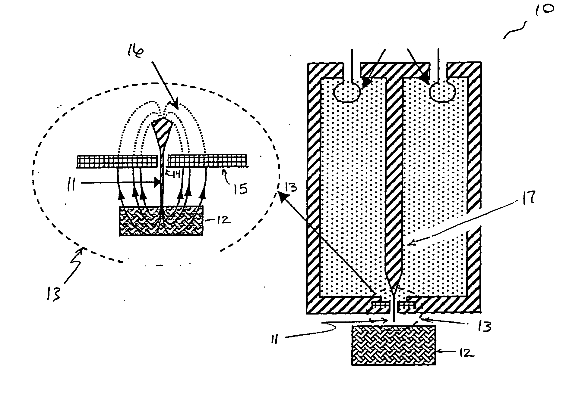
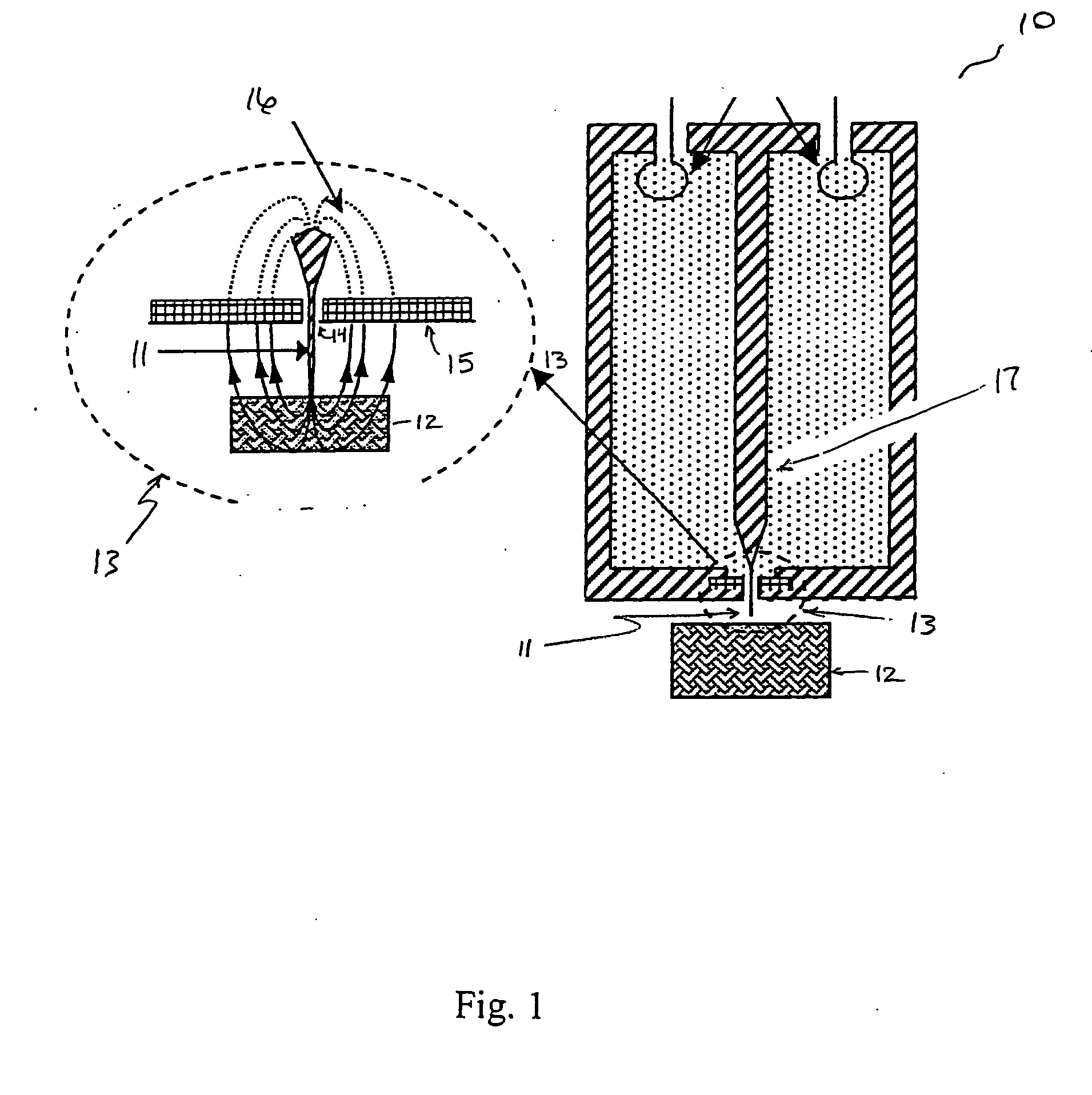
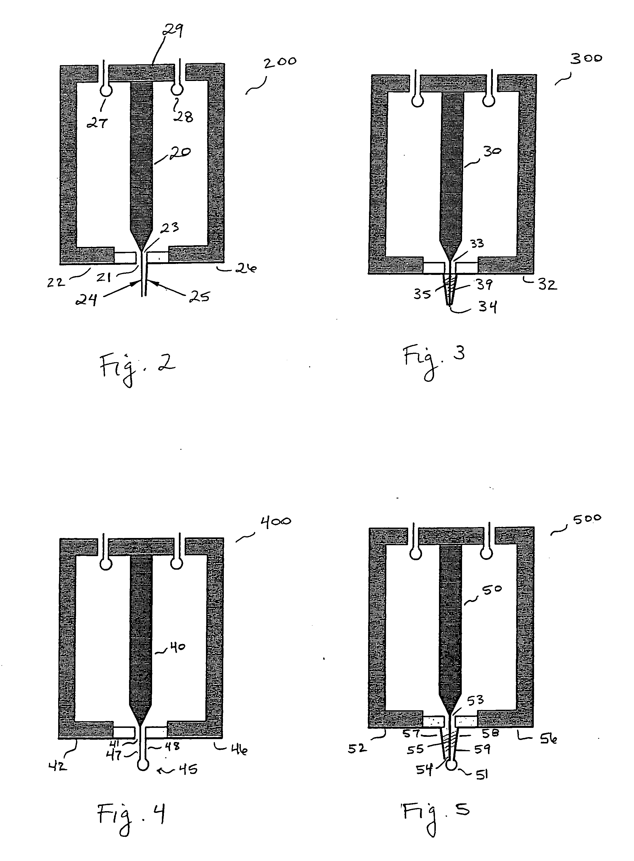
[0019] Embodiments of the present invention are directed to a novel evanescent microwave probes (EWP) designed to measure physical properties of a sample with enhances sensitivity and resolution, simultaneously. In one embodiment, new shielding features are added to the probe (which may be of either a sharpened tip or loop configuration) to reduce the effects of residual far field radiation, while maintaining the probe section that extends beyond the shielding aperture of the resonator. It will be understood by those skilled in the art, however, that the quality factor (Q) of the resonator may decrease, sometimes significantly, after the inventive shielding structures are added. A reduced quality factor may reduce the sensitivity of the probe system. To overcome this sensitivity issue caused by the novel shielding feature, an automatic gain-controlled active feedback loop system may be added to the probe resonator to form a self-oscillator. This new active circuit feature significantly increases the effective Q of the resonator probe, enhancing the sensitivity of both the frequency and Q measurement. The integrated EWP having the inventive shielding and active circuit feedback loop enhances both resolution and sensitivity simultaneously, an effect which is contemplated to enable many applications in materials and biotechnology areas.

Problems solved by technology

A reduced quality factor may reduce the sensitivity of the probe system.

Method used


Image

  • Evanescent microwave probe with enhanced resolution and sensitivity
  • Evanescent microwave probe with enhanced resolution and sensitivity
  • Evanescent microwave probe with enhanced resolution and sensitivity

Examples


Embodiment Construction

[0031] The present inventors have developed a novel scanning evanescent microwave probe (SEMP) having a shielding structure that is designed to confine propagating far-field components to the resonant cavity. Thus, only non-propagating evanescent waves are generated at the tip of the probe. The inventors had also developed theoretical models to obtain near-field analytical solutions to the relevant mathematical equations, the models allowing for quantitative measurements to be made of the electrical impedance of materials in the microwave domain with sub-micron resolution. These developments represented significant progress in the field of non-destructive and quantitative electrical impedance measurements, and they could be applied to a wide range of materials ranging from insulating dielectrics, to semiconductors, to highly conducting metals. The EMP disclosed previously emits evanescent microwaves into the sample via a conducting tip that is part of the probe; the same tip of the ...


PUM


Abstract

Novel systems of an evanescent microwave probe (EWP) are disclosed, which enable measurements of physical properties of a sample with enhanced sensitivity and resolution, simultaneously. In one embodiment, new shielding features are added to the probe (which may be of either a sharpened tip or loop configuration) to reduce the effects of residual far field radiation, while maintaining the probe section that extends beyond the shielding aperture of the resonator. To further increase the sensitivity of the instrument, an automatic gain-controlled active feedback loop system may be added to the probe resonator to form a self-oscillator. This new active circuit feature significantly increases the effective Q of the resonator probe, enhancing the sensitivity of both the frequency and Q measurement.

Description

PRIORITY CLAIM [0001] This Application claims priority to U.S. Provisional Patent Application No. 60 / 587,311, filed Jul. 12, 2004, entitled Evanescent Microwave Probe with Enhanced Resolution and Sensitivity.BACKGROUND OF THE INVENTION [0002] 1. Field of the Invention [0003] Embodiments of the present invention are directed in general to high resolution and high-sensitivity detection and / or profiling of the electromagnetic impedance of a substance. More specifically, the present invention is directed to systems and methods that use an evanescent wave probe. [0004] 2. State of the Art [0005] In the discussion of the state of the art that follows, reference is made to certain structures and / or methods. However, the following references should not be construed as an admission that these structures and / or methods constitute prior art. Applicants expressly reserve the right to demonstrate that such structures and / or methods do not qualify as prior art against the present invention. Clas...

Claims


Application Information

Patent Timeline
IPC IPC(8): G01R31/02
CPCB82Y20/00G01Q60/22G01Q10/065B82Y35/00
Inventor XIANG, XIAO-DONGYANG, HAITAOWANG, GANG
Owner INTEMATIX
Learn More