Flat resolver

a technology of resolver and rotor, which is applied in the field of resolver, can solve the problems of increasing power consumption, affecting the winding of transformers, and affecting the winding of transformers, and achieves the effects of reducing power consumption, high-precision resolver, and stabilizing gaps

Inactive Publication Date: 2006-06-15
MINEBEA CO LTD
View PDF1 Cites 9 Cited by
  • Summary
  • Abstract
  • Description
  • Claims
  • Application Information

AI Technical Summary

Benefits of technology

[0024] An object of an illustrative, non-limiting embodiment of the present invention is to provide a flat resolver which has a magnetic path which forms a magnetic flux effectively linking to a secondary winding and a detection winding and has a uniform gap between a stator portion and a movable portion so that a resolver signal can be output with high precision. Also, the present invention is not required to overcome the disadvantage described above, and an illustrative, non-limiting embodiment of the present invention may overcome a different disadvantage or may not overcome any disadvantages.
[0036] According to the present invention, the cores have the magnetic pole portion and the side wall portion, thereby making it possible to provide a magnetic path which forms a magnetic flux effectively linking to the secondary winding and the detection winding. Therefore, it is possible to effectively convert a generated magnetic flux to an output, while reducing a leakage magnetic flux.
[0037] By providing the magnetic pole portion and the side wall portion in the cores, it is possible to obtain a uniform gap between the stator core and the movable core, thereby making it possible to output a high-precision resolver signal.
[0038] With the flat resolver structure, it is possible to reduce a length thereof in an axial direction.
[0040] The stator core, the movable core, and the primary and secondary transformer winding cores are made of silicon steel (magnetic material). Therefore, it is possible to obtain stable gaps between the stator core and the movable core and between the primary transformer winding core and the secondary transformer winding core, thereby making it possible to output a high-precision resolver signal.
[0041] By providing a slit in the stator core and the movable core, a magnetic path can be concentrated or limited to the magnetic pole portion and the wall side portion, thereby making it possible to suppress a leakage magnetic flux and an influence on the transformer winding.

Problems solved by technology

Therefore, a magnetic gap is increased, leading to an increase in the power consumption.
In this case, a gap between the stator and the rotator is not uniform, so that magnetic coupling between the stator and the rotator is distorted due to the tilt.
Therefore, the gap between the stator and the rotator is not uniform due to the thickness of the resin layer on the conductive material, and the length in the axial direction between the stator and the rotator is increased.
Therefore, magnetic coupling between the stator and the rotator is deteriorated.
Therefore, the number of turns in the winding cannot be large.
It is difficult to obtain a large magnetic flux generated in the winding.

Method used


Image

  • Flat resolver
  • Flat resolver
  • Flat resolver

Examples


embodiment 1

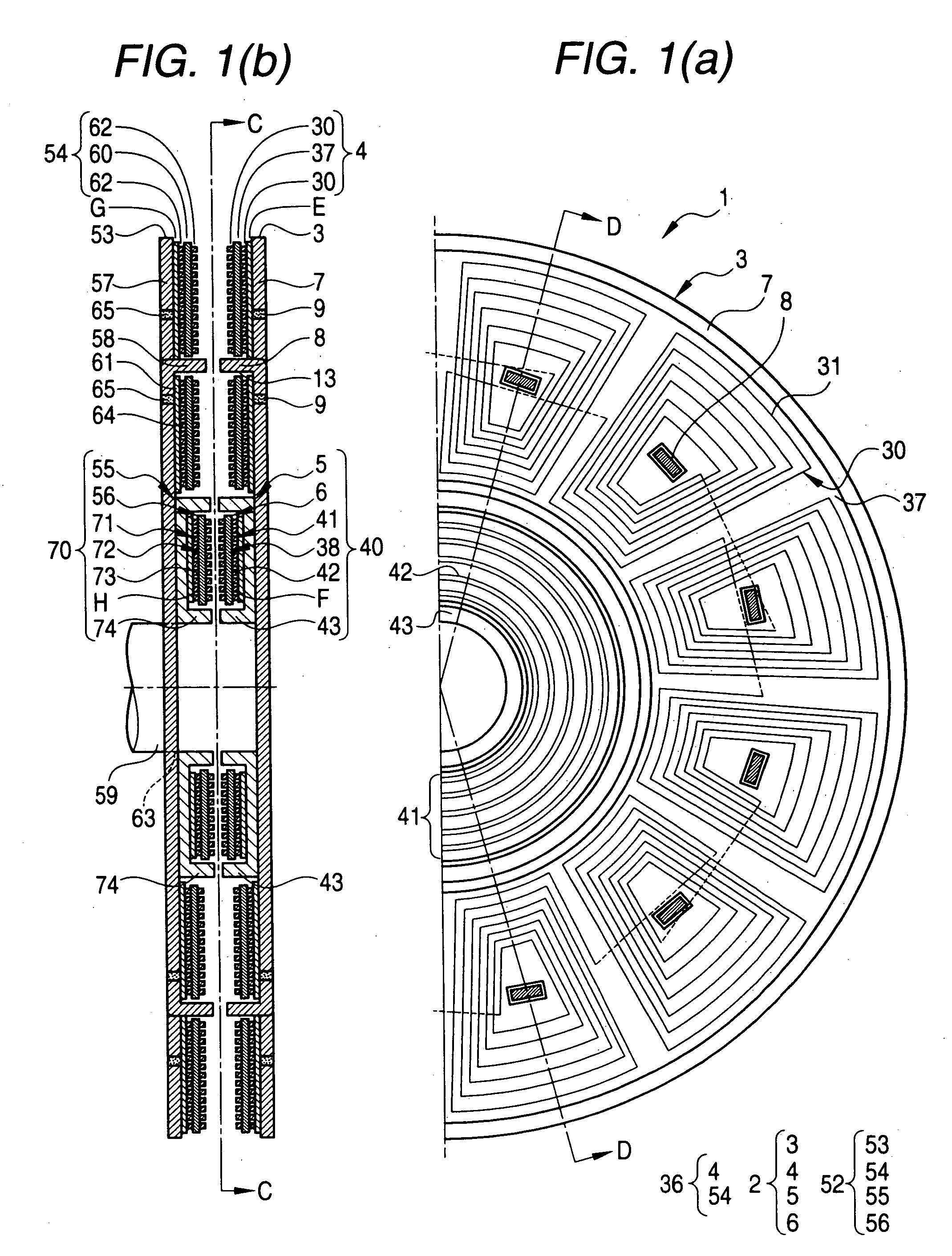
[0053] FIGS. 1(a) and 1(b) are structural diagrams illustrating a flat resolver of an exemplary embodiment of the present invention. Note that FIGS. 1(a) and 1(b) illustrates a half of the structure divided about a center axis thereof

[0054]FIG. 1(a) is a plan view illustrating a divided-half structure of a stator portion, taken along line C-C of FIG. 1(b) which is a cross-sectional view thereof FIG. 1(b) illustrates a cross-section of the flat resolver of the present invention, taken along line D-D of FIG. 1(a).

[0055] The flat resolver 1 of FIGS. 1(a) and 1(b) is a resolver which has transformer windings and has 6 pairs of magnetic poles and a gap in an axial direction with wiring substrates formed in disk-like shape. The flat resolver 1 includes a stator assembly 2 and a movable assembly 52.

(Stator Assembly)

[0056] A stator assembly 2 includes a stator core 3, a detection coil arranged-wiring substrate 4, a primary transformer winding core 5, and a primary transformer winding a...

embodiment 2

[0113] In Embodiment 1, the primary transformer winding core 5 and the secondary transformer winding core 55 of the transformer portion are prepared separately from the stator core 3 and the movable core 53, respectively. Since these cores are made of a magnetic material, the core portions of the transformer portion are integrated with the stator core 3 and the movable core 53 in Embodiment 2.

[0114] In this case, the core portion of the transformer portion has a side wall portion which is perpendicular to the plate portion of the stator core or the movable core. The side wall portion is obtained by cutting and bending a portion of the plate portion of the stator core or the movable core. Therefore, the cut-and-bent portion is not continuous as is different from the side wall portion.

[0115] By integrally forming the core portions of the transformer portions at portions of the stator core and the movable core, a process of forming a separate core portion of the transformer portion c...

embodiment 3

[0117] The number of magnetic pole pairs provided on the excitation coil arranged-wiring substrate and the number of magnetic pole pairs provided on the detection coil arranged-wiring substrate may be set so that N electrical output signal having one cycle (one cycle of sin output voltage signal) are output during one revolution of the shaft (mechanical angle: 360°). In this case, an N-fold axial angle (NX) can be achieved. The magnetic pole pairs can be changed by changing the excitation coil arranged-wiring substrate or the detection coil arranged-wiring substrate as appropriate.

[0118] Thus, characteristics of the resolver can be easily changed by selecting the various wiring substrates.

[0119] Similarly, the number of turns in the excitation coil or the detection coil can be changed so as to change characteristics of the resolver, by changing the various wiring substrates.

[0120] Similarly, by changing the various wiring substrates on which the transformer winding pattern is pro...


PUM

PropertyMeasurementUnit
thicknessaaaaaaaaaa
thicknessaaaaaaaaaa
mechanical angleaaaaaaaaaa

Abstract

A flat resolver, which has a magnetic path forming a magnetic flux effectively linking to a secondary winding and a detection winding and has a uniform gap between a stator portion and a movable portion so that a resolver signal can be output with high precision, is provided. The flat resolver includes: plate portions of a stator core and a movable core, which are made of a magnetic material and are disposed in parallel with each other; a plurality of magnetic pole portions protruding from opposed surfaces of the plate portions; coil arranged-wiring substrates disposed around each of the magnetic pole portions; transformer winding cores disposed on the plate portions; and transformer winding arranged-wiring substrates disposed on the transformer winding cores.

Description

BACKGROUND OF THE INVENTION [0001] 1. Field of the Invention [0002] The present invention relates to a resolver for detecting a rotational position, and more particularly, to a flat resolver having a transformer winding. [0003] 2. Description of the Related Art [0004] A related art resolver having a transformer winding for supply of a power source is illustrated in FIG. 7. [0005]FIG. 7 is a partially cross-sectional view of a related art resolver having a cylindrical stator assembly and a rotor assembly which is disposed coaxially with the cylindrical stator assembly. [0006] In FIG. 7, a resolver 100 has a cylindrical stator assembly 101, a rotor assembly 102 disposed coaxially with the stator assembly 101, and a transformer portion 103 including an inner core 104 and an outer core 105 disposed coaxially with the inner core 104. [0007] A stator portion includes the outer core 105 and the stator assembly 101, which are axially installed in a cylindrical housing 106. [0008] A rotor po...

Claims


Application Information

Patent Timeline
Patent Type & Authority Applications(United States)
IPC IPC(8): H01F21/04
CPCG01D5/2086
Inventor MIYA, TAIICHI
Owner MINEBEA CO LTD
Why Eureka
Try Eureka