
Substrate for inkjet recording head and inkjet recording head using the same

a technology of inkjet recording head and inkjet recording head, which is applied in printing and other directions, can solve the problems of inability to perform favorable ejection, fluctuation of ejection amount, and unstable ink-boiling phenomenon, and achieve the effect of increasing the size of the recording head and high density

Inactive Publication Date: 2006-06-15
CANON KK
View PDF15 Cites 26 Cited by
  • Summary
  • Abstract
  • Description
  • Claims
  • Application Information

AI Technical Summary

Benefits of technology

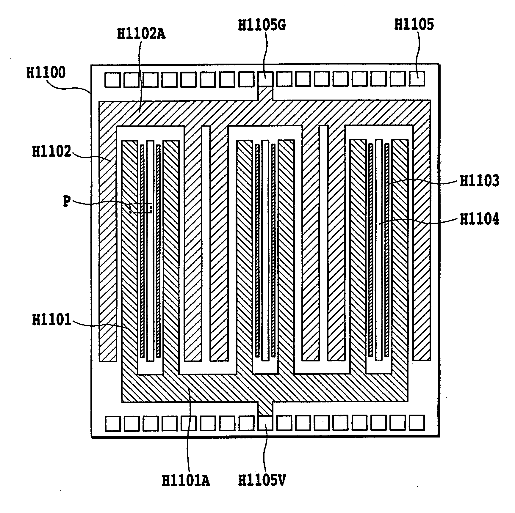
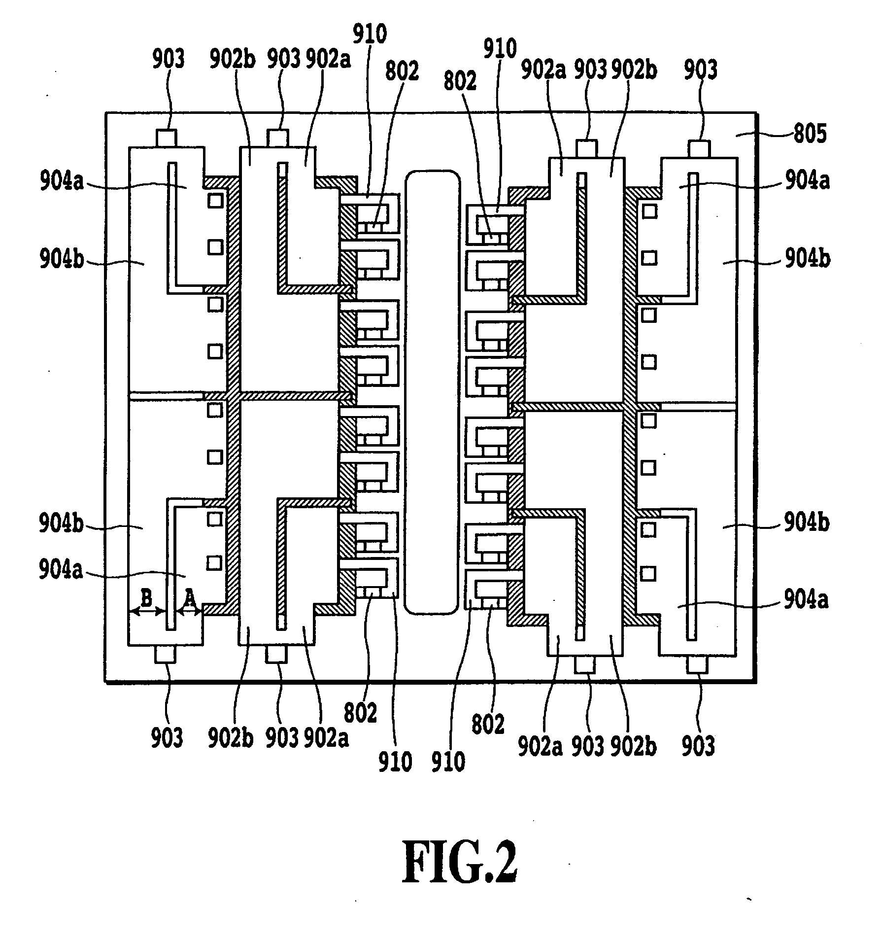
The present invention aims to solve the problem of limited heating and ejection openings in inkjet recording heads due to the number of electrode pads. The invention provides a substrate for an inkjet recording head with a high density of heating portions and ejection openings without increasing the size of the recording head. The substrate includes a plurality of arrays of recording elements, common power supply wires, and common ground wires that are collectively wired to the power supply-side electrode pad and the ground-side electrode pad. The combined resistance of common wiring portions is made substantially equal, allowing for more recording elements to be simultaneously driven within a required allowable range of voltage fluctuation and reducing the number of electrode pads to a minimum. The technical effect of the invention is to implement heating portions or ejection openings at a high density without increasing the size of the recording head.

Problems solved by technology

That is, when the applied electric energy varies, a foaming phenomenon also varies accordingly, and favorable ejection may not be performed.
For example, in the case where driving energy applied is small, an ink-boiling phenomenon is prone to become unstable because of an energy shortage.
This causes fluctuations in the ejection speed and ejection direction of ink and further causes fluctuations in the ejection amount.
These may cause a deterioration in the quality of a recorded image.
On the other hand, in the case where the applied driving energy is high, excessive thermal energy imposes mechanical stress on an electrothermal transducer or causes a change in film quality.
These may also cause an ejection failure as described above.
In extreme cases, the recording head may be broken.
Thus, in the case of known connection by individual wiring in units of the certain number of heating portions, the size of a substrate is greatly increased because of the number of electrode pads, and cost is increased.
On the other hand, there are demands for the downsizing of recent recording apparatuses.
Accordingly, in the case of known connection by individual wiring, it is very difficult to reduce the size of a substrate under the constraint that the size of a recording head cannot be easily increased as described above.

Method used


Image

  • Substrate for inkjet recording head and inkjet recording head using the same
  • Substrate for inkjet recording head and inkjet recording head using the same
  • Substrate for inkjet recording head and inkjet recording head using the same

Examples


Embodiment Construction

[0037] Hereinafter, the present invention will be described in detail with reference to drawings.

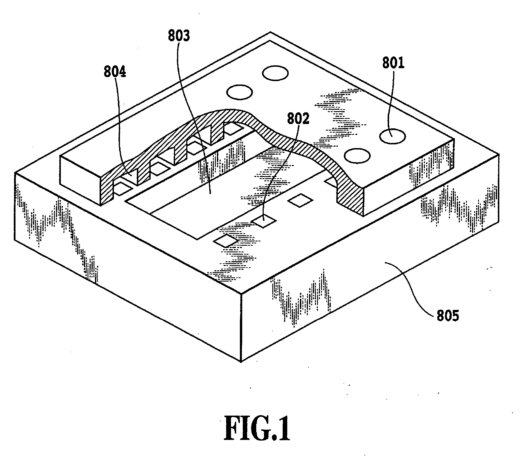
[0038]FIGS. 3A and 3B are perspective views illustrating a recording head cartridge H1000 to which a recording head H1001 according to one embodiment of the present invention can be applied. This recording head cartridge H1000 includes the recording head H1001 and ink tanks H1901, H1902, H1903, and H1904 which are provided to be attachable and detachable to / from the recording head H1001 as illustrated in FIG. 3B. It should be noted that these ink tanks are denoted by reference numeral H1900 in the case where they are not specified. These ink tanks may be ones corresponding to, for example, black, cyan, magenta, and yellow inks (recording liquid). The recording head H1001 ejects ink, which is supplied from the ink tanks H1900, from ejection openings in accordance with recording information.

[0039] This recording head cartridge H1000 is fixed and supported by positioning means and electri...


PUM


Abstract

Limitations on the number of recording elements capable of being simultaneously driven are relaxed so that driving voltage fluctuation falls within an allowable range. The substrate includes arrays of recording elements, common power supply wires extended from portions near one end portions of the arrays to portions near the other end portions thereof and connected to a power supply-side electrode pad through a position near the one end portions of the arrays, and common ground wires extended from portions near the one end portions of the arrays to portions near the other end portions thereof and connected to a ground-side electrode pad through a position near the other end portions of the arrays. Thus, since the sum of the lengths of common wires from the electrode pads is equal for all the plurality of elements included in each array, and the combined resistance of common wiring portions becomes substantially equal.

Description

BACKGROUND OF THE INVENTION [0001] 1. Field of the Invention [0002] The present invention relates to a substrate for an inkjet recording head which ejects ink onto a recording surface of a recording medium to perform recording operation, and to an inkjet recording head using the same. An inkjet recording head suitable for applying the present invention has a plurality of ink supply ports which are shaped like long grooves and which lead ink from the opposite surface (backside) of the substrate from the surface where elements for generating energy used to eject ink are arranged, through the substrate to the elements. Furthermore, the inkjet recording head is one which ejects ink in a direction perpendicular to the plane of the substrate in response to the driving of the elements. [0003] 2. Description of the Related Art [0004] Inkjet recording heads applied to recording apparatuses which perform recording by imparting ink to recording media such as recording paper include ones which ...

Claims


Application Information

Patent Timeline
Patent Type & Authority Applications(United States)
IPC IPC(8): B41J2/05
CPCB41J2/14072
Inventor KUBO, KOUSUKEIMANAKA, YOSHIYUKIHATSUI, TAKUYATAKEUCHI, SOUTAYAMAGUCHI, TAKAAKIMATSUI, TAKAHIRO
Owner CANON KK
Learn More