Illumination system for a microlithography projection exposure apparatus

a technology of exposure apparatus and exposure system, which is applied in the direction of microlithography exposure apparatus, printers, instruments, etc., can solve the problems of substantially codetermination between image quality and wafer throughput that can be achieved with the apparatus, and achieve the effect of small coheren

Inactive Publication Date: 2006-06-15
CARL ZEISS SMT GMBH
View PDF8 Cites 10 Cited by
  • Summary
  • Abstract
  • Description
  • Claims
  • Application Information

AI Technical Summary

Benefits of technology

[0009] It is one object of the invention to provide an illumination system for a microlithography projection exposure apparatus which permits the setting of very small degrees of coherence. It is another object to provide an illumination system for a microlithography projection exposure ...

Problems solved by technology

Furthermore, the image quality and the wafer throughput that can be achieved with the apparatus are subs...

Method used


Image

  • Illumination system for a microlithography projection exposure apparatus
  • Illumination system for a microlithography projection exposure apparatus
  • Illumination system for a microlithography projection exposure apparatus

Examples


Embodiment Construction

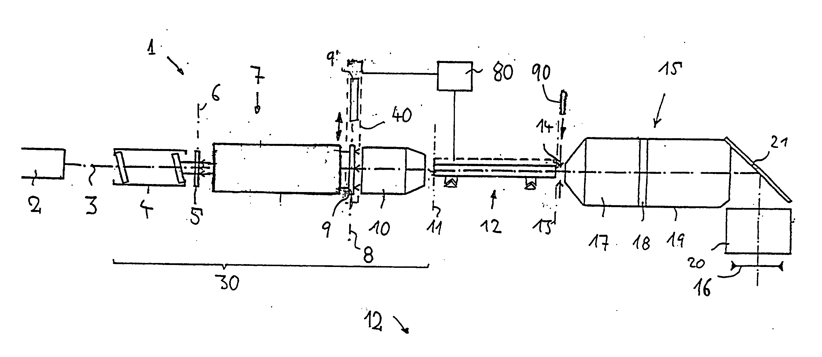
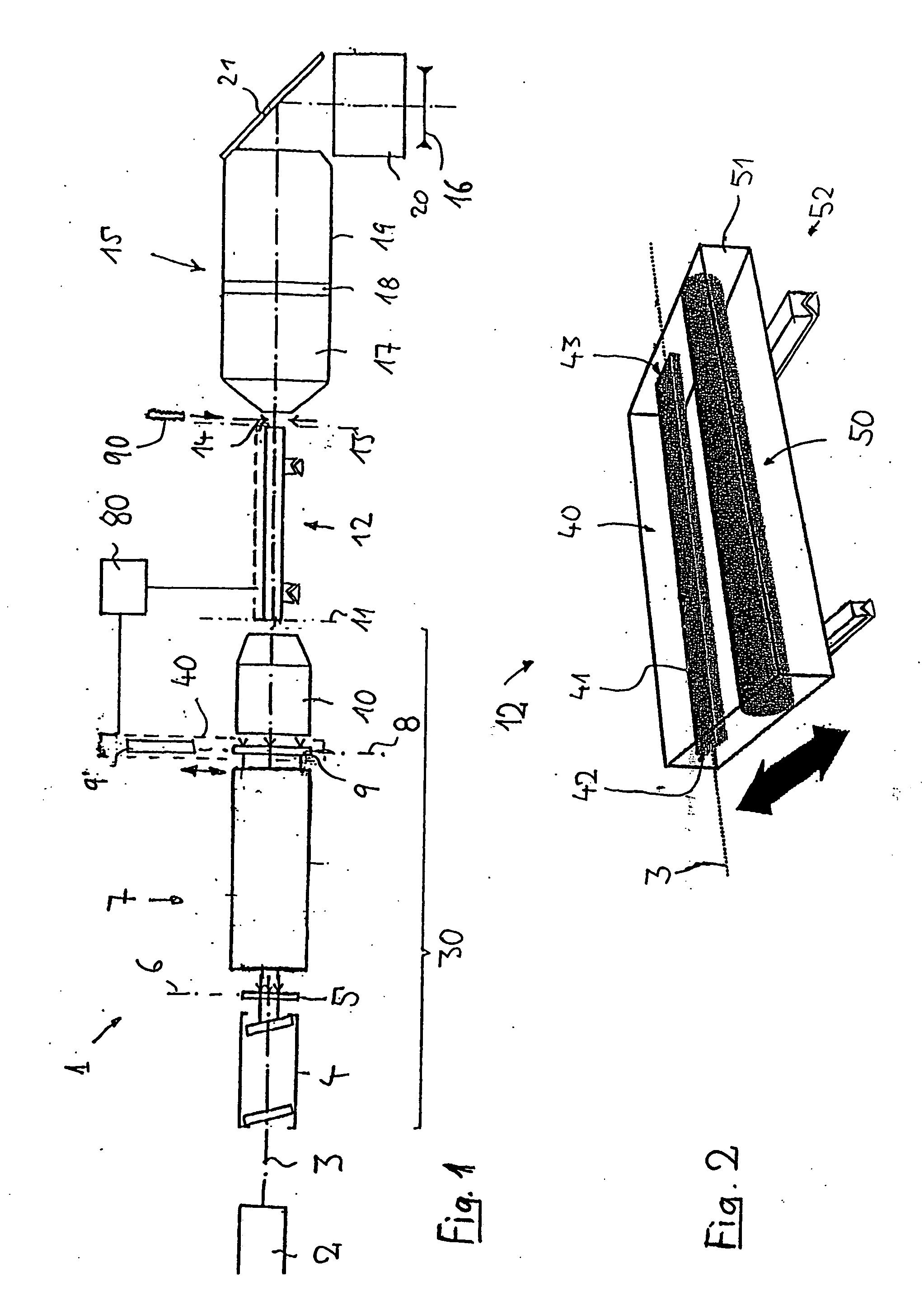
[0039]FIG. 1 shows an example of an illumination system 1 of a microlithographic projection exposure apparatus which can be used in the fabrication of semiconductor components and other finely patterned devices and operates with light from the deep ultraviolet range in order to obtain resolutions down to fractions of micrometers. The light source 2 used is an F2 excimer laser having an operating wavelength of approximately 157 nm, the light beam of which is oriented coaxially with respect to the optical axis 3 of the illumination system. Other UV light sources, for example ArF excimer lasers having an operating wavelength of 193 nm, KrF excimer lasers having an operating wavelength of 248 nm or mercury vapor lamps having an operating wavelength of 368 nm or 436 nm or light sources having wavelengths of less than 157 nm are likewise possible.

[0040] The light from the light source 2 firstly enters a beam expander 4, which may be designed for example as a mirror arrangement in accorda...


PUM


Abstract

An illumination system for a microlithography projection exposure apparatus is designed for illuminating an illumination field with an illumination radiation with a predeterminable degree of coherence σ, it being possible to adjust the degree of coherence within a degree of coherence range extending into the range of very small degrees of coherence of significantly less than σ=0.2. The illumination system may have a first optical system for generating a predeterminable light distribution in an entrance plane of a light mixing device, and also a light mixing device for homogenizing the impinging radiation. The first optical system and the light mixing device can in each case be changed over between a plurality of configurations corresponding to different degree of coherence ranges. The degree of coherence ranges overlap and are dimensioned such that the resulting total degree of coherence range is larger than the individual degree of coherence ranges.

Description

[0001] This application is a Continuation of International Patent Application PCT / EP2004 / 004875 filed on May 7, 2004, and claiming priority from German Patent Application DE 103 22 393.2 filed on May 12, 2003. Priority is claimed from German Patent Application DE 103 22 393.2 filed on May 12, 2003. The complete disclosure of these patent applications is incorporated into this application by reference.BACKGROUND OF THE INVENTION [0002] 1. Field of the Invention [0003] The invention relates to an illumination system for a microlithography projection exposure apparatus for illuminating an illumination field with illumination radiation with a predeterminable degree of coherence. [0004] 2. Description of the Related Art [0005] The performance of projection exposure apparatuses for the microlithographic fabrication of semiconductor components and other finely patterned devices is substantially determined by the imaging properties of the projection objectives. Furthermore, the image qualit...

Claims


Application Information

Patent Timeline
IPC IPC(8): G03B27/72G02B27/09G03FG03F7/20
CPCG03F7/70075G03F7/70091
Inventor DEGUENTHER, MARKUSWANGLER, JOHANNESBROTSACK, MARKUSMIZKEWITSCH, ELLA
Owner CARL ZEISS SMT GMBH
Why Eureka
Try Eureka