LED light source assembly

a technology of led light source and assembly, which is applied in the field of electric lamps, can solve the problems of shortening the life of leds, grouped structures that cannot provide an adequate cumulative intensity, and insufficient individual luminous output to replace most other lamp forms, and achieves good thermal dissipation and intensive led positioning

Inactive Publication Date: 2006-06-15
OSRAM SYLVANIA INC
View PDF3 Cites 35 Cited by
  • Summary
  • Abstract
  • Description
  • Claims
  • Application Information

AI Technical Summary

Benefits of technology

[0004] A compact LED light source providing intensive LED positioning along with good thermal dissipation can be made with a heat conductive plate supporting a plurality of LEDs mounted in thermal contact with the plate. The plate further supports electrical circuitry providing an electrical connection to the LEDs. A heat conductive stem mechanically supports the plate and may provide an electrical conduction path and a thermal conduction path away from the LEDs.

Problems solved by technology

Presently they have insufficient individual luminous output to replace most other lamp forms (incandescent, tungsten halogen, fluorescent, and high intensity discharge).
Because the individual LEDs are necessarily spaced apart, the grouped structures can fail to provide an adequate cumulative intensity.
They may also produce high heat concentrations that shorten LED life.
Because LEDs need to be individually wired into the grouped structure, such assemblies can require tedious or expensive assembly.

Method used


Image

  • LED light source assembly
  • LED light source assembly
  • LED light source assembly

Examples


Embodiment Construction

[0017] A light source assembly may be formed from a heat conductive plate, supporting a plurality of LEDs; and connecting electrical circuitry. A heat conductive stem to duct heat from the plate supports the plate. The stem may be further supported on a base.

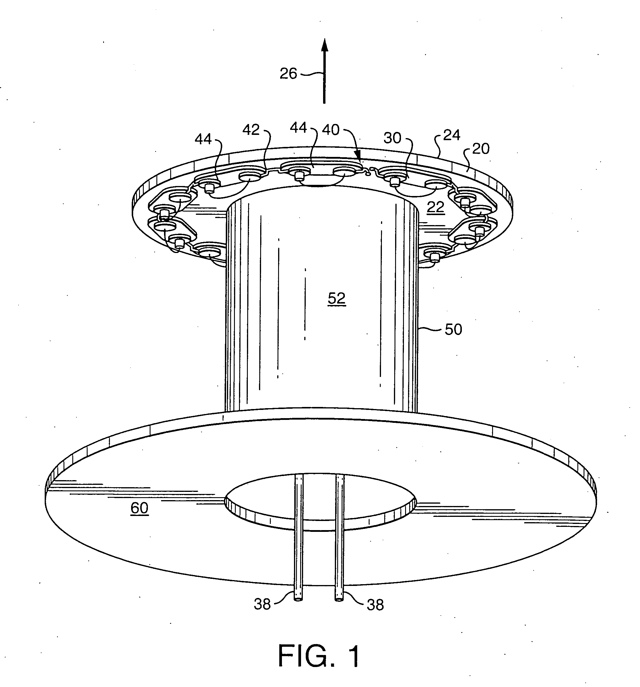
[0018]FIG. 1 shows a schematic design of a simple plate 20 supporting a plurality of LED light sources 30 connected by circuit traces (electrical circuitry 40). The LEDs 30 are mounted on circuitry pads 44. The preferred plate 20 may be formed from a metal or circuit board material with an inner side 22 and an outer side 24 facing in a forward direction 26. The plate 20 is a substantially solid, heat conductive piece. It is preferably round to enable rotational processing during LED mounting and assembly. It is a convenient aspect of the circular plate structure, that the plate 20 may be axially mounted in a machine for indexed rotation to LED mounting stations. The plate 20 may then be populated with LEDs 30 by indexed rotatio...


PUM


Abstract

A compact LED light source providing intensive LED positioning along with thermal dissipation can be made with a heat conductive plate supporting a plurality of LEDs mounted on the plate and in thermal contact with the plate. The plate further supports electrical circuitry providing electrical connection to the LEDs. A heat conductive stem mechanically supports the plate and may provide a thermal conduction path from the plate away from the LEDs. A high concentration of LED can then be conveniently mounted and held in close proximity for increased optical system intensity, while providing a thermal exit path for the associated increase in heat concentration.

Description

[0001] The Applicants hereby claim the benefit of their provisional application, Ser. No. 60 / 371,015 filed Apr. 9, 2002 for Snap Together Automotive LED Lamp Assembly; and Ser. No. 60 / 490,493 filed Jul. 28, 2003 for LED Light Source Assembly.TECHNICAL FIELD [0002] The invention relates to electric lamps and particularly to electric lamps using LED light sources. More particularly the invention is concerned with LED light sources supported on a heat conductive plate in a reflector type lighting assembly. BACKGROUND ART [0003] LEDs offer both increased lamp life and electrical efficiency. Presently they have insufficient individual luminous output to replace most other lamp forms (incandescent, tungsten halogen, fluorescent, and high intensity discharge). LEDs can be grouped together to accumulate sufficient light output to compete with some of the other light sources. Because the individual LEDs are necessarily spaced apart, the grouped structures can fail to provide an adequate cumu...

Claims


Application Information

Patent Timeline
Patent Type & Authority Applications(United States)
IPC IPC(8): F21V7/00F21V29/00F21K99/00F21S8/04F21V19/00F21Y101/02H01L25/075
CPCF21K9/00F21V7/0008F21V29/004F21Y2101/02H01L25/0753F21V29/74H01L2924/0002F21V29/20F21V29/505H01L2924/00F21Y2115/10
Inventor COUSHAINE, CHARLES M.
Owner OSRAM SYLVANIA INC
Why Eureka
Try Eureka