Compressor sound suppression

a compression machine and sound suppression technology, applied in the field of compression machines, can solve the problems of increasing the pressure of the trapped gas in the rotor, and achieve the effect of reducing the effective volume of a portion

Active Publication Date: 2006-06-15
CARRIER CORP
View PDF2 Cites 19 Cited by
  • Summary
  • Abstract
  • Description
  • Claims
  • Application Information

AI Technical Summary

Benefits of technology

[0011] In various implementations, the placing may locate the blind volume in a wall of the housing. The selecting may include an iterative process of varying the at least one geometric parameter and directly or indirectly determining the pressure pulsation parameter (e.g., until a minimum or a desired threshold has been met). The determining may include measuring a sound intensity at a target frequency for pulsation. The placing may include inserting a plug into a compartment in the housing. The plug may have an aperture defining a Helmholz resonator port. The plug may reduce an effective volume of a portion of the compartment. The placing may include extending a blind terminal portion of a compartment in the housing.

Problems solved by technology

Furthermore, the feeding of gas into the rotors after suction is cut off increases the pressure of the trapped gas in the rotors.

Method used


Image

  • Compressor sound suppression
  • Compressor sound suppression
  • Compressor sound suppression

Examples


Embodiment Construction

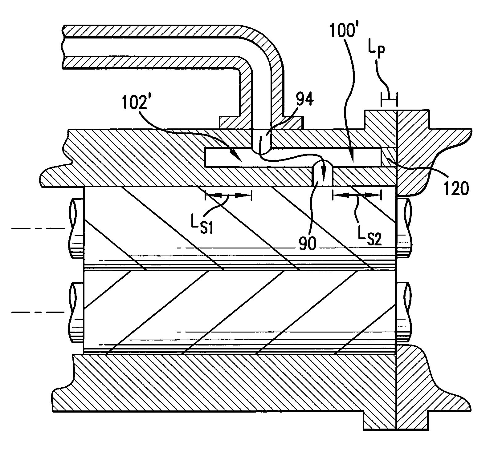
[0019]FIG. 1 shows a compressor 20 having a housing assembly 22 containing a motor (not shown) driving rotors 26 and 28 having respective central longitudinal axes 500 and 502. In the exemplary embodiment, the rotor 26 has a male lobed body or working portion 30 extending between a first end 31 and a second end 32. The working portion 30 is enmeshed with a female lobed body or working portion 34 of the female rotor 28. The working portion 34 has a first end 35 and a second end 36. Each rotor includes shaft portions (e.g., stubs 39, 40, 41, and 42 unitarily formed with the associated working portion) extending from the first and second ends of the associated working portion. Each of these shaft stubs is mounted to the housing by one or more bearing assemblies (not shown) for rotation about the associated rotor axis.

[0020] In the exemplary embodiment, the motor is an electric motor having a rotor and a stator. One of the shaft stubs of one of the rotors 26 and 28 may be coupled to th...


PUM

PropertyMeasurementUnit
pressureaaaaaaaaaa
volumeaaaaaaaaaa
pressure pulsationaaaaaaaaaa

Abstract

A compressor has a housing. One or more working elements cooperate with the housing to define a compression path between suction and discharge locations. An intermediate port is located along the compression path. A branch path extends to the intermediate port. The compressor includes means for limiting pressure pulsations along the branch path.

Description

BACKGROUND OF THE INVENTION [0001] The invention relates to compressors. More particularly, the invention relates to compressors having economizer ports. [0002] Screw-type compressors are commonly used in air conditioning and refrigeration applications. In such a compressor, intermeshed male and female lobed rotors or screws are rotated about their axes to pump the working fluid (refrigerant) from a low pressure inlet end to a high pressure outlet end. During rotation, sequential lobes of the male rotor serve as pistons driving refrigerant downstream and compressing it within the space between an adjacent pair of female rotor lobes and the housing. Likewise sequential lobes of the female rotor produce compression of refrigerant within a space between an adjacent pair of male rotor lobes and the housing. The interlobe spaces of the male and female rotors in which compression occurs form compression pockets (alternatively described as male and female portions of a common compression p...

Claims


Application Information

Patent Timeline
Patent Type & Authority Applications(United States)
IPC IPC(8): F04B49/00
CPCF04C18/086F04C18/16F04C29/0035Y10T29/49238F04C29/068Y10T29/49242F04C29/061F25B2500/12F04B39/12F04B51/00
Inventor SHOULDERS, STEPHEN L.
Owner CARRIER CORP
Why Eureka
Try Eureka