Energy storage device

a technology of energy storage and energy density, which is applied in the direction of liquid electrolytic capacitors, electrochemical generators, cell components, etc., can solve the problems of low energy density, poor discharge characteristics at large current, and inability to deteriorate input/output characteristics, etc., and achieve excellent input/output characteristics and high storage energy density

Inactive Publication Date: 2006-06-15
HITACHI LTD
View PDF0 Cites 19 Cited by
  • Summary
  • Abstract
  • Description
  • Claims
  • Application Information

AI Technical Summary

Benefits of technology

[0010] The present invention can provide an energy storage device excelle...

Problems solved by technology

However, the existent lithium secondary battery involves a problem that the charge/discharge characteristics are poor at a large cur...

Method used


Image

  • Energy storage device
  • Energy storage device
  • Energy storage device

Examples


example 1

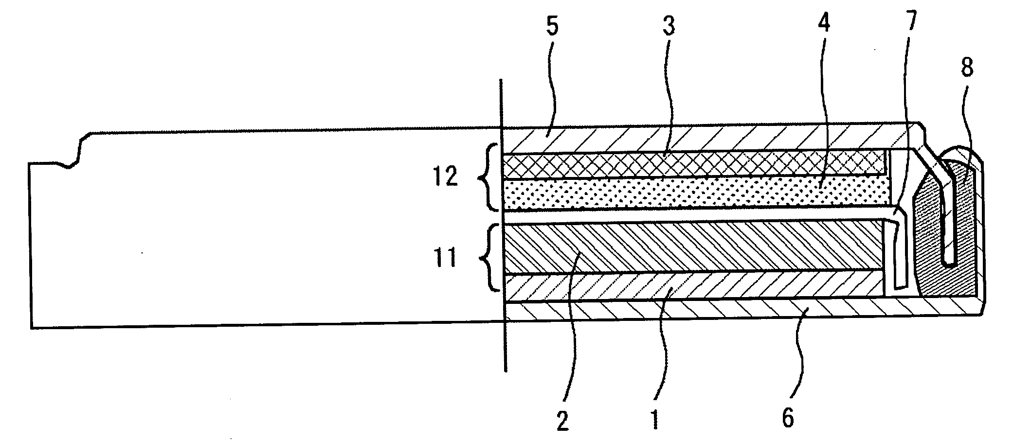
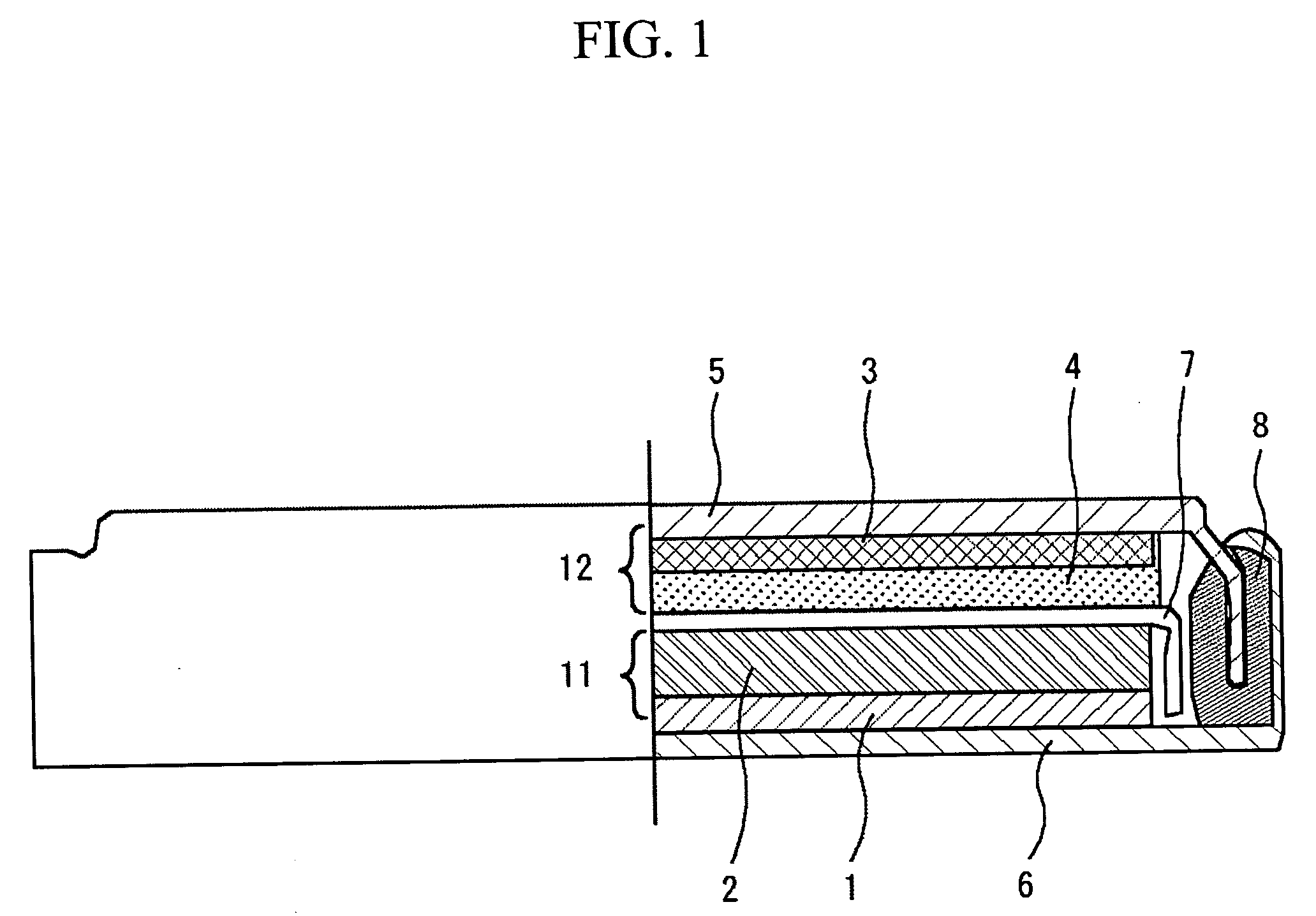
[0062] A coin shaped energy storage device was manufactured with a constitution shown in FIG. 1.

[0063] At first, a cathode comprising a material layer conducting the non-faradic reaction was manufactured on a cathode faradic layer.

[0064] The cathode material was made of LiMn0.35Nix0.35Co0.30O2 of 10 μm in average particle diameter.

[0065] As the conductive aid, graphitic carbon with an average grain size of 3 μm and a specific surface area of 13 m2 / g, and carbon black with an average grain size of 0.04 μm and a specific surface area of 40 m2 / g mixed at 4:1 weight ratio was used.

[0066] As the binder, a solution in which polyvinylidene fluoride was previously dissolved by 8 wt % in N-methyl pyrrolidone was used.

[0067] Then, the cathode active material, the conductive aid and the polyvinylidene fluoride mixed at a weight ratio of 85:10:5 and kneaded sufficiently was used as the cathode slurry. The cathode slurry was coated and dried on one surface of a cathode collector comprising ...

example 2

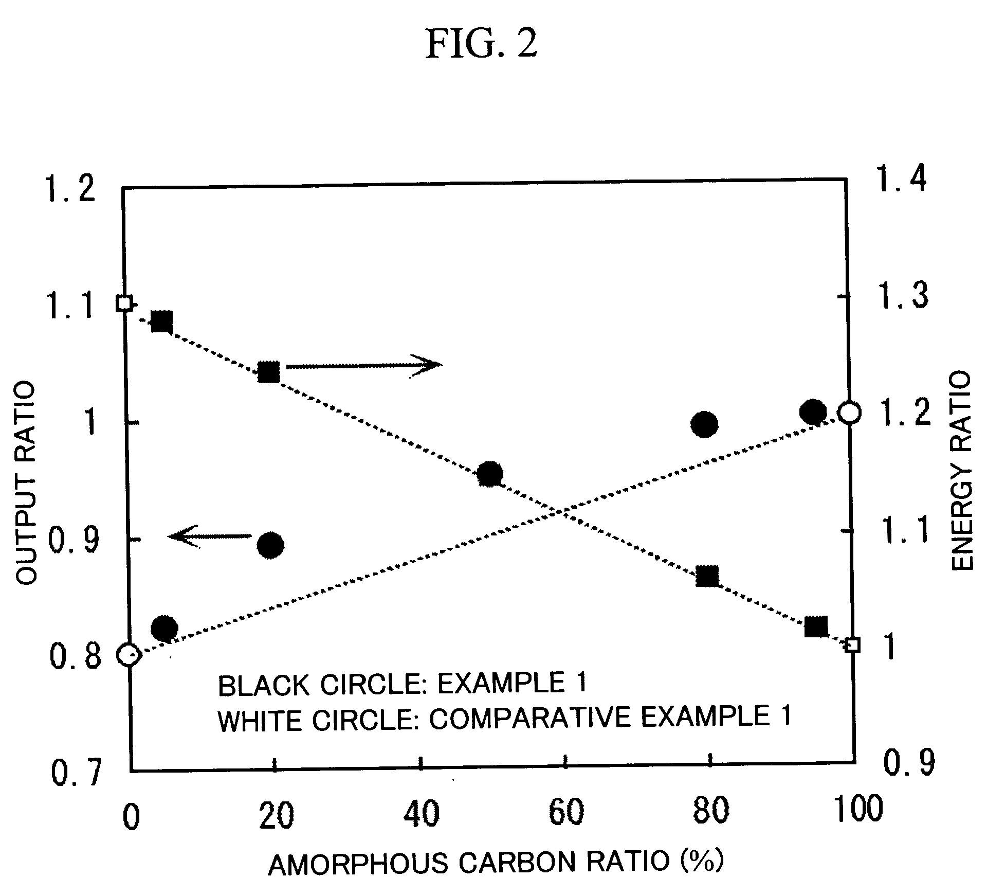
[0083] As the energy storage device of Example 2, a carbon black layer with a specific surface area of 40 m2 / g like the cathode was disposed on the anode and the energy storage device was manufactured in the same manner as in Example 1 than described above. The mixing ratio between amorphous carbon and graphite in the anode mix in Example 2 was set to 80:20, 50:50, and 20:80.

example 3

[0091] In Example 3, the cathode of Example 1 was changed to a cathode comprising a mix formed by mixing the material conducting the faradic reaction and the material conducting the non-faradic reaction which was used as a cathode and the energy storage device like in Example 1 was manufactured.

[0092] A cathode mix layer was prepared such that the same cathode material, the conductive aid, the polyvinylidene fluoride (activated carbon / cathode active material: 19 wt %) and active carbon as in Example 1 were at the weight ratio of 68:10:6:16. The energy storage device was manufactured in the same manner as in Example 1 only except for the charge of the ratio. The mixing ratio between the amorphous carbon and graphite in the anode mix in Example 3 was controlled to 80:20, 50:50, and 20:80.


PUM


Abstract

An energy storage device of excellent input/output characteristics and having high density of stored energy, the device having a cathode comprising a material conducting faradic reaction and a material conducting non-faradic reaction, and an anode comprising a material conducting faradic reaction, in which the faradic reaction is desorption/intercalation reaction of lithium ions, higher input/output characteristics being obtainable by providing a mix layer comprising a material conducting faradic reaction on a cathode collector and providing a material layer conducting non-faradic reaction further to the surface layer thereof.

Description

FIELD OF THE INVENTION [0001] The present invention concerns an energy storage device for storing and releasing electric energy. BACKGROUND OF THE INVENTION [0002] In recent years, a power source of higher input and output than usual has been demanded as a power source for electric vehicles, hybrid electric vehicles or electromotive tools, and a power source being capable of charging and discharging more rapidly and increased with capacity has been demanded. [0003] Particularly, a power source with less dependence on temperature and capable of maintaining input / output characteristics even at a low temperature of −20° C. to −30° C. [0004] The demand described above has been coped with by improving the performance of a secondary battery such as a lithium secondary battery, nickel hydrogen battery, nickel cadmium battery or lead battery mainly having faradic reaction mechanism in combination with the use of an electric double layer capacitor having favorable input / output characteristic...

Claims


Application Information

Patent Timeline
IPC IPC(8): H01M4/58H01G9/042H01M4/02H01M4/131H01M4/36H01M10/05H01M10/0525
CPCH01G9/155H01M4/131H01M4/366H01M4/485H01M4/587H01M10/0525H01M10/058Y02E60/122Y02E60/13Y02E60/10H01G11/06H01G11/32H01G11/50
Inventor YAMAKI, TAKAHIROARAI, JUICHIKUMASHIRO, YOSHIAKI
Owner HITACHI LTD
Why Eureka
Try Eureka