Turbine engine rotor stack

a technology of turbine engines and rotor stacks, which is applied in the direction of machines/engines, stators, liquid fuel engines, etc., to achieve the effect of increasing the rotational speed

Active Publication Date: 2006-06-22
RAYTHEON TECH CORP
View PDF9 Cites 117 Cited by
  • Summary
  • Abstract
  • Description
  • Claims
  • Application Information

AI Technical Summary

Benefits of technology

[0008] In various implementations, the second means may include spacers (e.g., as in the Suciu et al. applications or otherwise). The first means may comprise radial splines or interfitting first and second pluralities of teeth on the first and second disks, respectively. The first plurality of teeth may be formed at an aft rim of a first sleeve extending aft from and unitarily-formed with a web of the first disk. The second plurality of teeth may be formed at a forward rim of a second sleeve extending forward from and unitarily-formed with a web of the second disk. The first and second disks may each have an inboard annular protuberance inboard of the respective first and second sleeves. The second means may comprise a spacer having an outwardly longitudinally concave portion having a thickness and a longitudinal extent effective to provide an increase in said force with an increase in rotational speed of the first and second disks. The engine may have a high speed and pressure turbine section a

Problems solved by technology

However, some spacers are often separate from at least one of the adjacent pair of

Method used


Image

  • Turbine engine rotor stack
  • Turbine engine rotor stack
  • Turbine engine rotor stack

Examples


Embodiment Construction

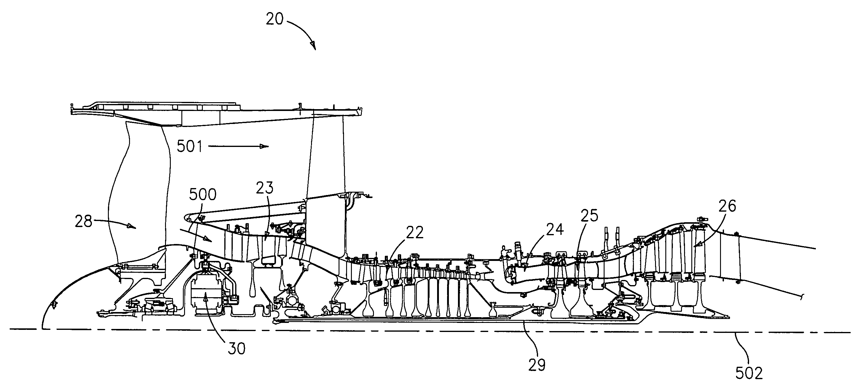
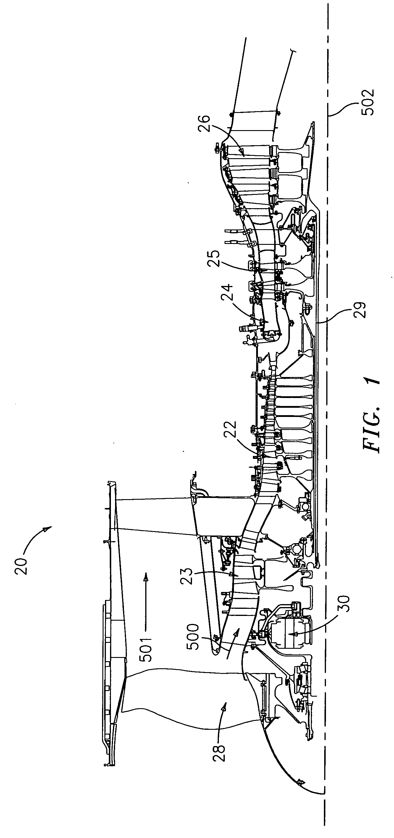
[0014]FIG. 1 shows a gas turbine engine 20 having a high speed / pressure compressor (HPC) section 22 receiving air moving along a core flowpath 500 from a low speed / pressure compressor (LPC) section 23 and delivering the air to a combustor section 24. High and low speed / pressure turbine (HPT, LPT) sections 25 and 26 are downstream of the combustor along the core flowpath 500. The engine further includes a fan 28 driving air along a bypass flowpath 501. Alternative engines might include an augmentor (not shown) among other systems or features.

[0015] The exemplary engine 20 includes low and high speed spools mounted for rotation about an engine central longitudinal axis or centerline 502 relative to an engine stationary structure via several bearing systems. A low speed shaft 29 carries LPC and LPT rotors and their blades to form a low speed spool. The low speed shaft 29 may be an assembly, either fully or partially integrated (e.g., via welding). The low speed shaft is coupled to the...


PUM


Abstract

A turbine engine has a first disk and a second disk, each extending radially from an inner aperture to an outer periphery. A coupling, transmits a torque and a longitudinal compressive force between the first and second disks. The coupling has first means for transmitting a majority of the torque and a majority of the force and second means, radially outboard of the first means, for vibration stabilizing.

Description

BACKGROUND OF THE INVENTION [0001] The invention relates to gas turbine engines. More particularly, the invention relates to gas turbine engines having center-tie rotor stacks. [0002] A gas turbine engine typically includes one or more rotor stacks associated with one or more sections of the engine. A rotor stack may include several longitudinally spaced apart blade-carrying disks of successive stages of the section. A stator structure may include circumferential stages of vanes longitudinally interspersed with the rotor disks. The rotor disks are secured to each other against relative rotation and the rotor stack is secured against rotation relative to other components on its common spool (e.g., the low and high speed / pressure spools of the engine). [0003] Numerous systems have been used to tie rotor disks together. In an exemplary center-tie system, the disks are held longitudinally spaced from each other by sleeve-like spacers. The spacers may be unitarily-formed with one or both...

Claims


Application Information

Patent Timeline
IPC IPC(8): F02K3/04
CPCF01D5/066F01D11/001F05D2260/4031
Inventor SUCIU, GABRIEL L.NORRIS, JAMES W.
Owner RAYTHEON TECH CORP
Why Eureka
Try Eureka